Reel base assembly

a technology of spool and base plate, which is applied in the field of reels, can solve the problems of vibration and impact force originating from the support surface and/or the spool traveling through the base plate,

Inactive Publication Date: 2007-05-10
REELCRAFT INDS
View PDF23 Cites 14 Cited by
  • Summary
  • Abstract
  • Description
  • Claims
  • Application Information

AI Technical Summary

Benefits of technology

[0009] The present invention provides a base assembly for a reel, such as a hose reel, including two cooperating base components joined to one another and supporting a spool assembly. The base components may be identical to one another, and each include a base portion and an upright portion disposed 90° with respect to one another and formed monolithically from a single piece of material such as steel. The base components further include rigidifying structures such as gussets, edge bends, and reinforcement ribs or channels to rigidify the base components against vibration and impact stresses. Each of the base portions includes a connection plate and an offset connection flange, wherein the connection flanges overlap and are secured to respective connection plates when the upright components are mated and secured to one another with one upright component disposed at an orientation rotated 180° with respect to the other. The base assembly may be attached to a surface, such as a floor, wall, or other surface via suitable fasteners, and the connections between the upright components are substantially isolated from vibration and impact stresses imposed upon on the base assembly. In one exemplary embodiment, the connection between the base components may be varied to provide modularity to the base assembly. In this embodiment, the base assembly may be configured to support spool assemblies of various dimensions.

Problems solved by technology

Although base assemblies of the type shown in FIGS. 1 and 2 have proven to be satisfactorily durable and effective in use, a potential disadvantage of same is that vibration and impact forces originating from the support surface and / or the spool travel through base plate 12 and uprights 14, and tend to produce stress concentrations at the connections of uprights 14 to base plate 12 and, in particular, at weld beads 16 and fasteners 18.

Method used


Image

  • Reel base assembly
  • Reel base assembly
  • Reel base assembly

Examples


Embodiment Construction

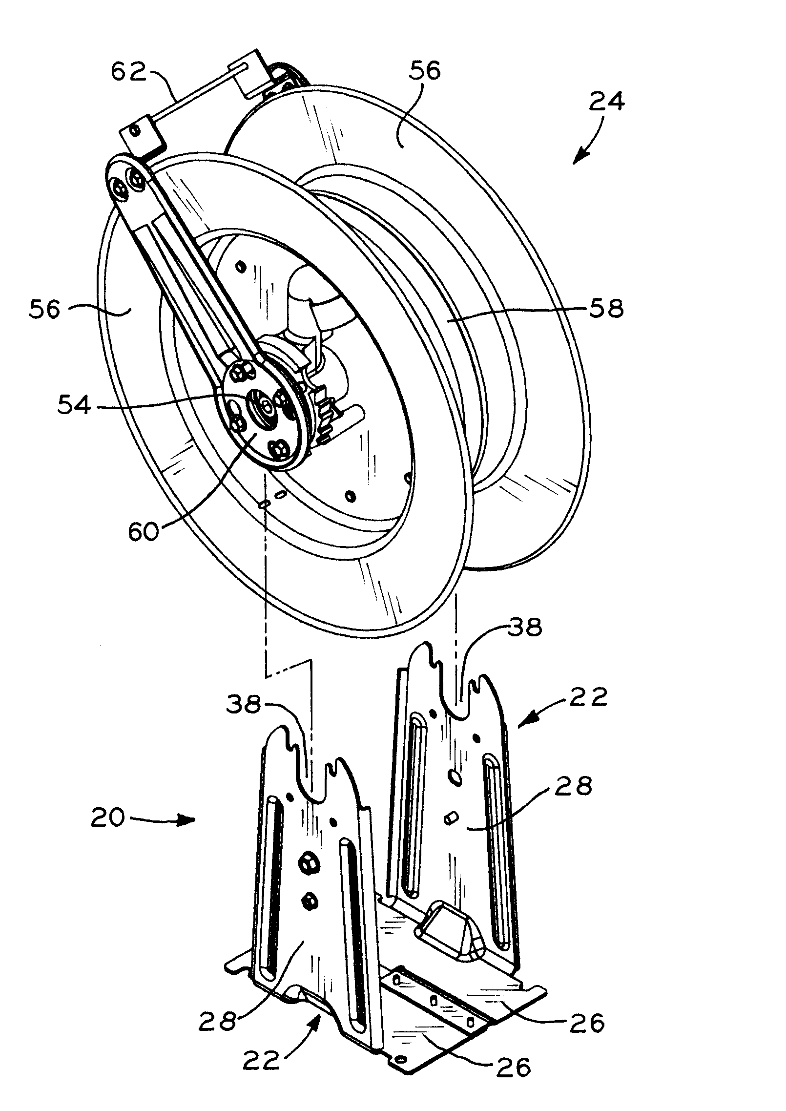
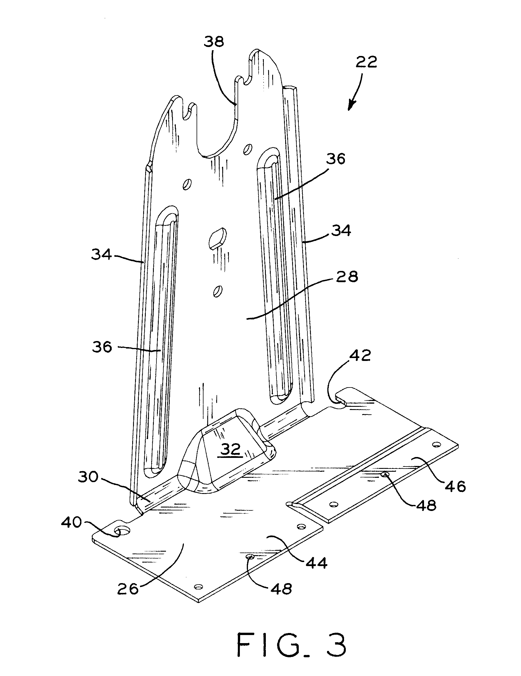
[0029] Referring to FIG. 3, one of the two base components 22 of base assembly 20 (FIG. 4) of a reel in accordance with the present invention is shown. As described below and shown in FIGS. 4-7, two identical base components 22 are connected to one another to form base assembly 20, which supports spool assembly 24 (FIGS. 6 and 7) to store and to facilitate the use of a hose, cord, rope, cable, or other flexible elongate item. Although base components 22 are described herein as identical, base components 22 need not be identical, wherein one or both of the base components 22 may include one or more structural features which are different from the other.

[0030] Each base component 22 may be formed monolithically from a single piece of metal, such as steel or aluminum, by stamping, punching, and / or bending operations, and generally includes base portion 26 and upright portion 28 oriented approximately 90° with respect to one another. Base portion 26 and upright portion 28 are connected...


PUM


Abstract

A base assembly for a reel, such as a hose reel, including two cooperating base components joined to one another and supporting a spool assembly. The base components may be identical to one another, and each include a base portion and an upright portion disposed 90° with respect to one another and formed monolithically from a single piece of material such as steel. The base components further include rigidifying structures such as gussets, edge bends, and reinforcement ribs or channels to rigidify the base components against vibration and impact stresses. Each of the base portions includes a connection plate and an offset connection flange, wherein the connection flanges overlap and are secured to respective connection plates when the upright components are mated and secured to one another with one upright component disposed at an orientation rotated 180° with respect to the other. The base assembly may be attached to a surface, such as a floor, wall, or other surface via suitable fasteners, and the connections between the upright components are substantially isolated from vibration and impact stresses imposed upon on the base assembly. In one exemplary embodiment, the connection between base components may be varied to provide modularity to the base assembly. In this embodiment, the base assembly may be configured to support spool assemblies of various dimensions.

Description

CROSS REFERENCE TO RELATED APPLICATIONS [0001] This application claims the benefit under Title 35, U.S.C. §119(e) of U.S. Provisional Patent Application Ser. No. 60 / 734,209, entitled REEL BASE ASSEMBLY, filed on Nov. 7, 2005.BACKGROUND OF THE INVENTION [0002] 1. Field of the Invention [0003] The present invention relates to reels for storing hoses, electrical and data cords, ropes, cables, or other items. In particular, the present invention relates to a reel including an improved base assembly. [0004] 2. Description of the Related Art [0005] Reels are used to store a variety of flexible elongate items such as hoses for delivering fluids, including water, air, hydraulic fluid, or grease, for example. The hoses may be round or flat in shape, and may also be used in vacuum applications for removing a fluid or a solid substance from a given location. Reels are also used to store other flexible elongate items, such as electrical and data cords, ropes, cables, and the like. [0006] Referr...

Claims


Application Information

Patent Timeline
Patent Type & Authority Applications(United States)
IPC IPC(8): B65H75/44
CPCB65H75/446B65H75/4402
Inventor FRANKLIN, JAMES R.STERNEMAN, WALTER P. IIBRAUN, JOSHUA T.
Owner REELCRAFT INDS
Why Eureka
Try Eureka