Gas Turbine Regenerator Apparatus and Method of Manufacture

Active Publication Date: 2010-06-10
MUND 2013 FAMILY TRUST +2
View PDF13 Cites 34 Cited by
  • Summary
  • Abstract
  • Description
  • Claims
  • Application Information

AI Technical Summary

Benefits of technology

[0018]A plurality of reinforcing hoops are installed between adjacent plates, the hoops being positioned respectively between pairs of adjacent plates about the manifold regions thereof. The plates are joined together in sealing relationship, each hoop being configured to extend from one adjacent plate to the next and overlap a common juncture of said plates, the hoops being joined in structural reinforcing relationship to the adjacent surfaces of said plates. Each hoop has a generally U-shaped cross se

Problems solved by technology

Compressor discharge air, at the relatively high operating pressures encountered, tends to warp or bow the end frame structures of these devices, thereby presenting a point of potential material failure.
Also, the design of the prior art units have, to some extent, been limited in their recommended operating temperature ranges by virtue of the materials employed in their fabrication as well as by the fabricating techniques which were employed.
For example, the previously used compression-fin designs at times developed unbalanced internal pressure-area forces

Method used


Image

  • Gas Turbine Regenerator Apparatus and Method of Manufacture
  • Gas Turbine Regenerator Apparatus and Method of Manufacture
  • Gas Turbine Regenerator Apparatus and Method of Manufacture

Examples


Embodiment Construction

[0026]The embodiments of the invention presented in the following written description and the various features and advantageous details thereof are explained more fully with reference to the non-limiting examples included in the accompanying drawings and detailed in the description which follows. Descriptions of well-known components and processes and manufacturing techniques are omitted so as to not unnecessarily obscure the principle features of the invention as described herein. The examples used in the description which follows are intended merely to facilitate an understanding of ways in which the invention may be practiced and to further enable those skilled in the art to practice the invention. Accordingly, the examples should not be construed as limiting the scope of the claimed invention.

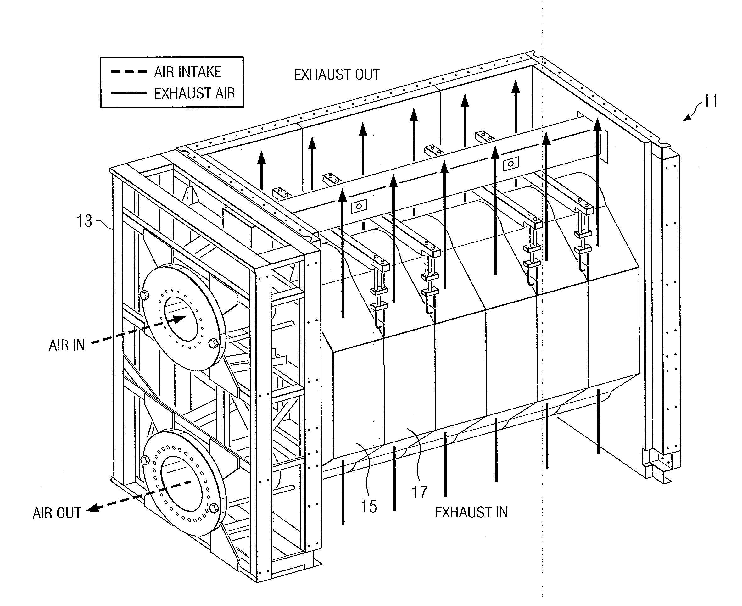
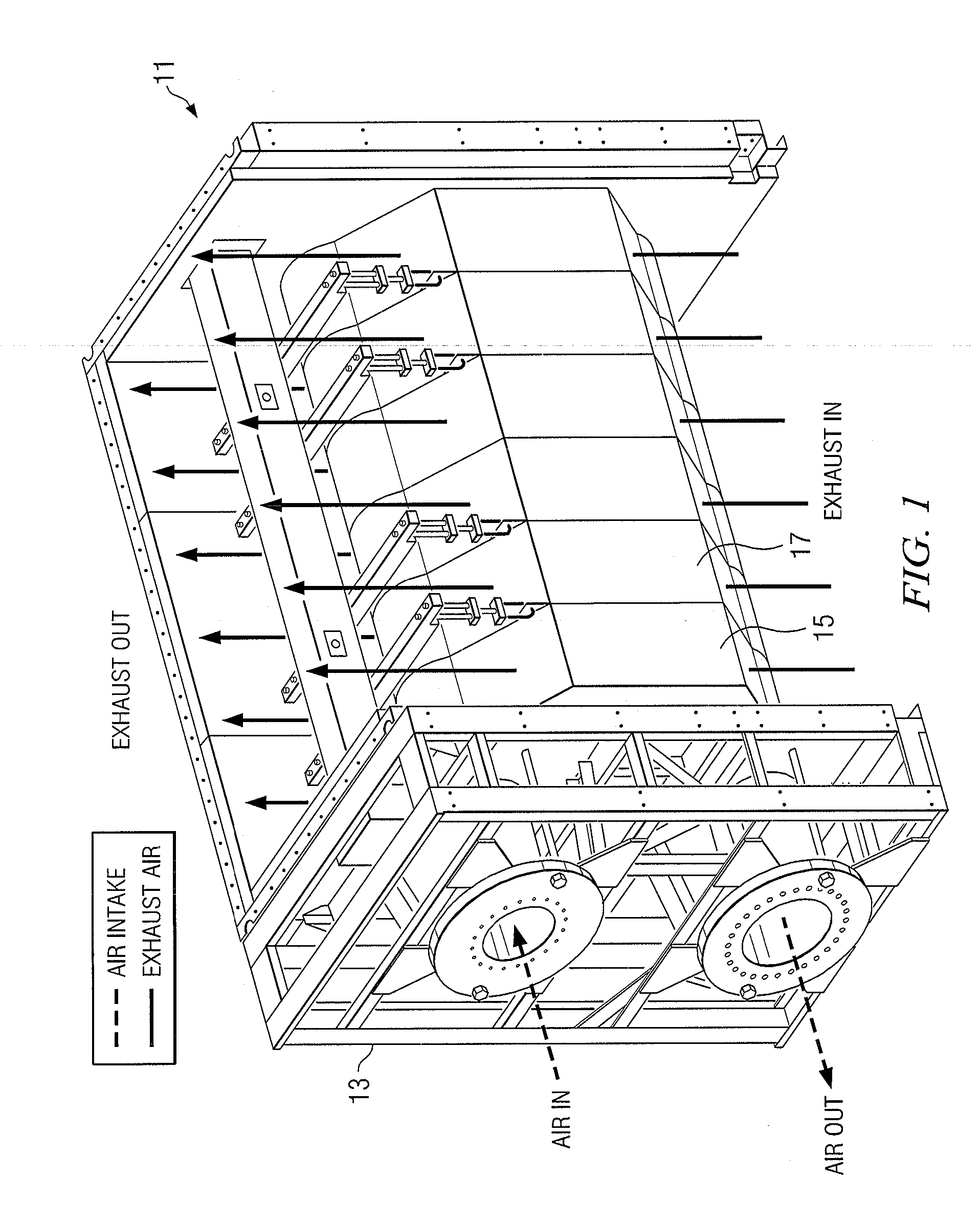
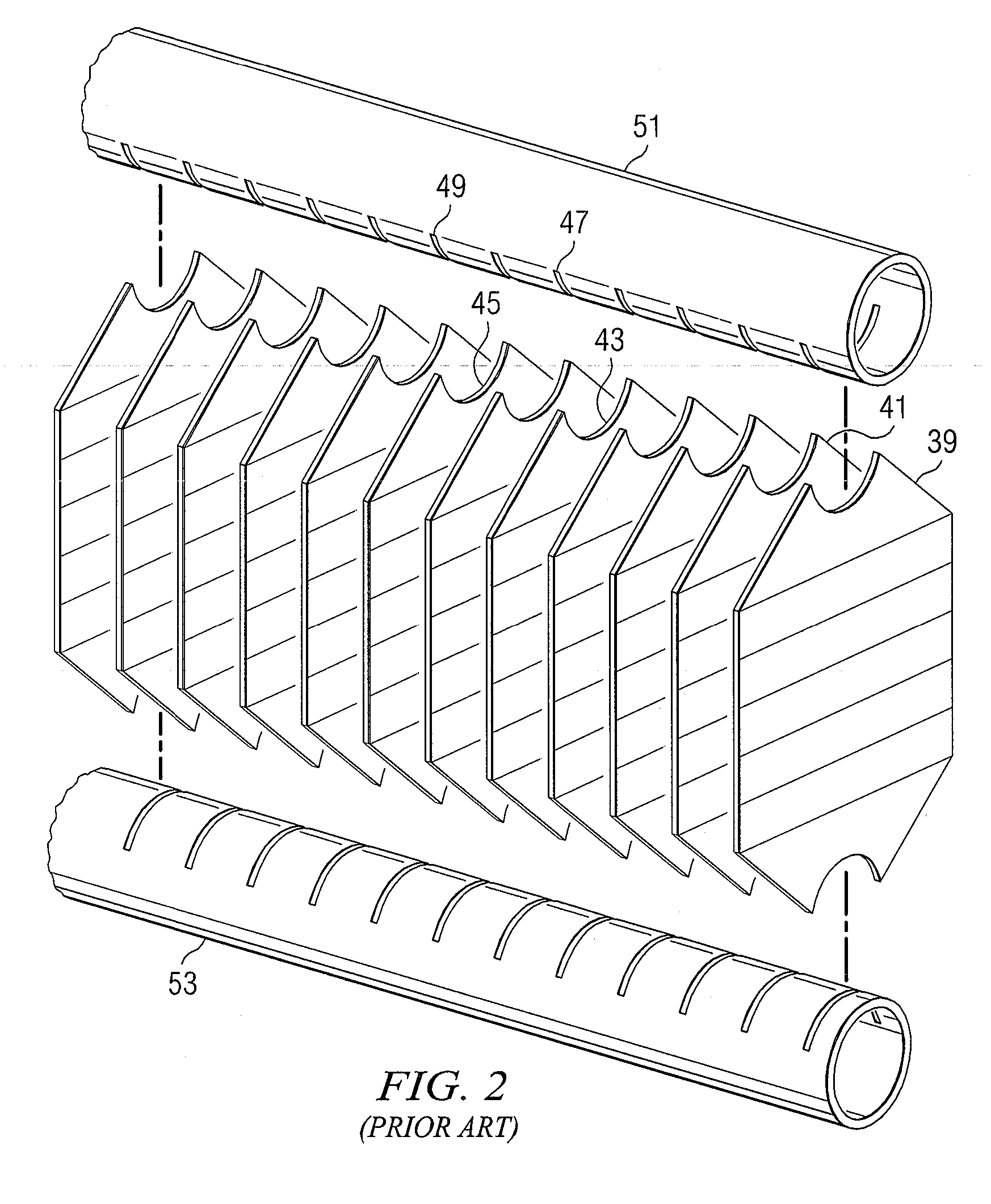
[0027]As has been mentioned previously, the present invention is an improvement in the design and manufacturing technique used in manufacturing a particular type of heat exchanger known in ...


PUM

PropertyMeasurementUnit
Pressureaaaaaaaaaa
Electrical resistanceaaaaaaaaaa

Abstract

A regenerator core for use in a gas turbine regenerator has integral manifold openings formed in the tube plates used to make up the core and has special reinforcing elements which provide high pressure containment in critical portions of the plate-and-fin heat exchanger construction. The reinforcing elements include a series of hoops of U-shaped cross section which are used to bridge the juncture lines of the heat exchanger manifolds. An outer channel region of the hoops is provided with a reinforcing strip of gusset material. The hoops with their reinforcing strips provide structural reinforcement in the region between the manifolds and the conventional side bar reinforcing members in the central core section.

Description

CROSS-REFERENCE TO RELATED APPLICATIONS[0001]The present application claims priority from the earlier filed provisional application Ser. No. 61 / 120,504 filed Dec. 8, 2008, entitled “Gas Turbine Regenerator Apparatus and Method of Manufacture,” by the same inventor.BACKGROUND OF THE INVENTION[0002]1. Field of the Invention[0003]This invention relates to methods and materials for manufacturing a specialized type of plate and fin type heat exchanger and, in particular, to a method and materials for manufacturing a gas turbine regenerator heat exchanger.[0004]2. Description of the Prior Art[0005]The present invention deals with a particular type of plate and fin heat exchanger known in the relevant arts as the “gas turbine regenerator.” This type of heat exchanger has been developed for use with large gas turbines for improving turbine efficiency and performance while reducing operating costs. Heat exchangers of the type under discussion are typically referred to as either “recuperators...

Claims


Application Information

Patent Timeline
IPC IPC(8): F02C7/10F28F3/02B23P15/26
CPCF28D9/0043F28D9/0062F28D21/001F28F3/025F28F9/0075F28F9/026Y10T29/49357Y10S165/906F28F2225/00F28F9/0221F28F2240/00Y10T29/49366F28F2225/08
Inventor THOMPSON, RANDY
Owner MUND 2013 FAMILY TRUST
Why Eureka
Try Eureka