Ejectable aerodynamic stability and control

a technology of aerodynamic stability and control, applied in the field of ejectable grid fins, can solve problems such as limitations of conventional grid fins and grid fin assemblies

Active Publication Date: 2007-05-10
RAYTHEON CO
View PDF7 Cites 16 Cited by
  • Summary
  • Abstract
  • Description
  • Claims
  • Application Information

AI Technical Summary

Benefits of technology

[0005] In various representative aspects, the present invention provides an ejectable grid fin assembly for use with aeronautic vehicles. Exemplary features generally include a grid array structure adapted for releasable engagement with, for example, a missile. The grid array may be configured with a plurality of grid cell turbulation surfaces to provide control forces for altering the flight performance characteristics of the combination of the grid fin with the missile as compared with the flight performance characteristics of the missile by itself.

Problems solved by technology

There are several limitations associated with conventional fins and grid fin assemblies.

Method used


Image

  • Ejectable aerodynamic stability and control
  • Ejectable aerodynamic stability and control
  • Ejectable aerodynamic stability and control

Examples


Embodiment Construction

[0011] The following representative descriptions of the present invention generally relate to exemplary embodiments and the inventors' conception of the best mode, and are not intended to limit the applicability or configuration of the invention in any way. Rather, the following description is intended to provide convenient illustrations for implementing various embodiments of the invention. As will become apparent, changes may be made in the function and / or arrangement of any of the elements described in the disclosed exemplary embodiments without departing from the spirit and scope of the invention.

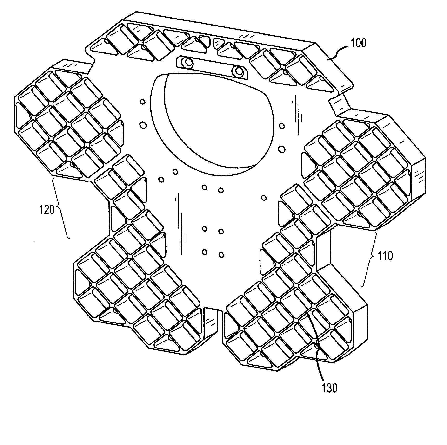
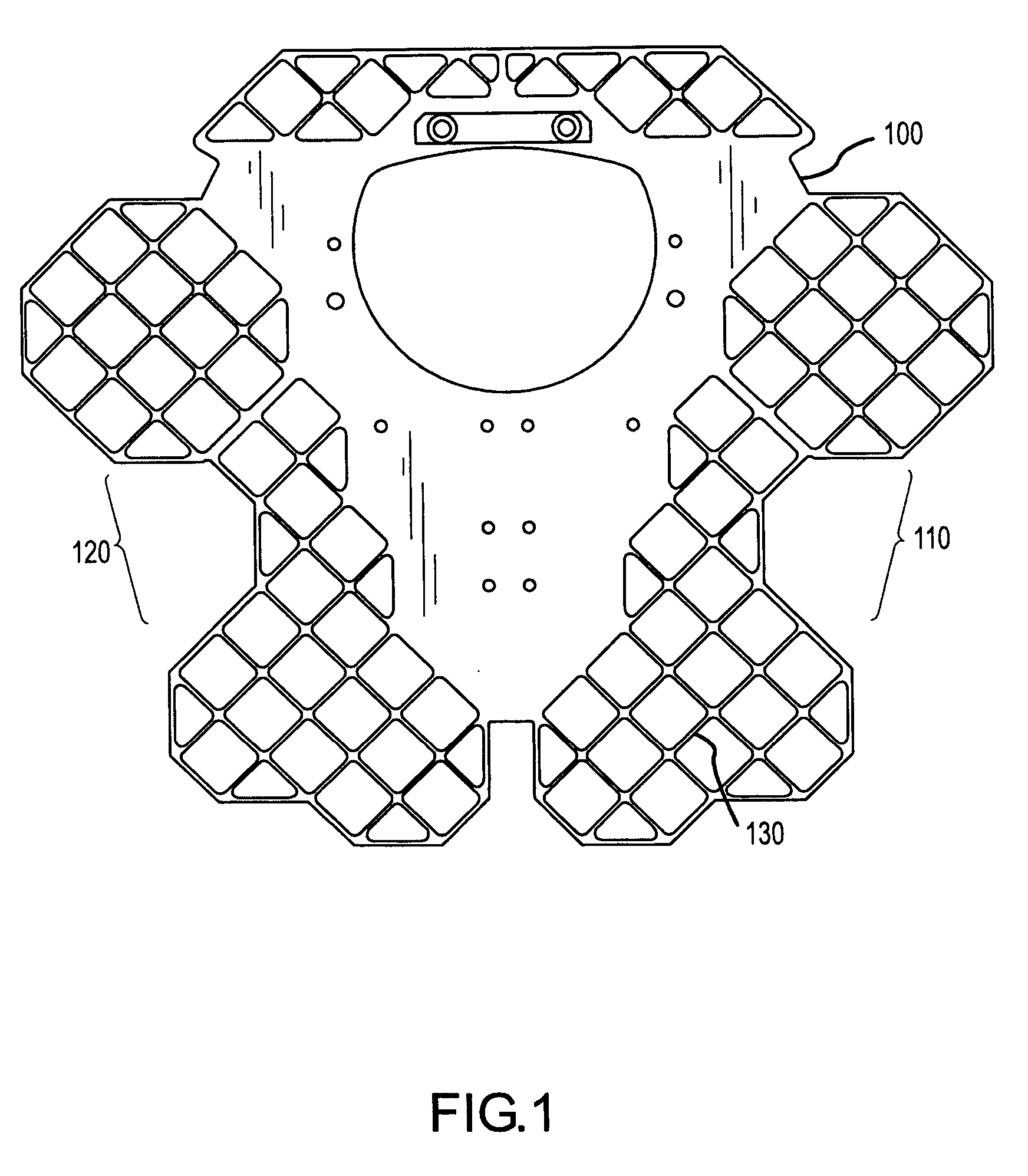
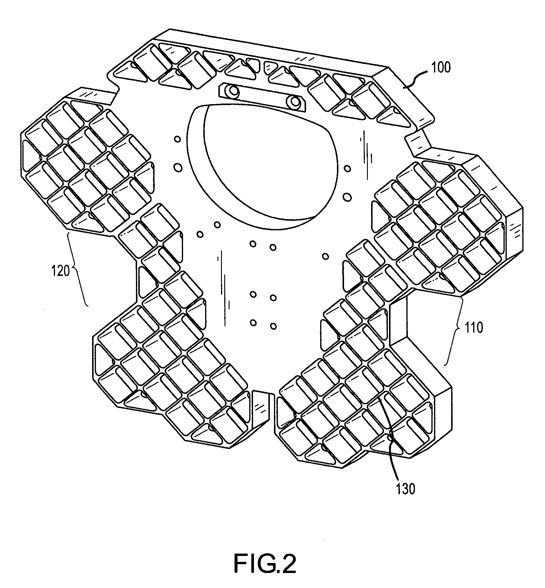
[0012] A detailed description of an exemplary embodiment, namely an ejectable grid fin adapted for releasable engagement with a missile, is provided as a specific enabling disclosure that may be generalized to any application of the disclosed system, device and method for improving aerodynamic stability and / or control of an aeronautic vehicle in accordance with various other embodiment...


PUM


Abstract

The disclosed system and method for improving aerodynamic stability of aeronautic vehicles generally includes an ejectable grid fin adapted for releasable engagement with aeronautic vehicles. The grid fin is generally configured to optimize the flight performance characteristics of the aeronautic vehicle taken in engaged combination with the grid fin as compared with the flight performance of the aeronautic vehicle taken alone. Disclosed features and specifications may be controlled, adapted or otherwise optionally modified to improve the aerodynamic stability and/or control of a variety of deployed aeronautic vehicles. Exemplary embodiments of the present invention generally provide ejectable grid fins that may be used in conjunction with missiles mounted on an eject rail of an aircraft.

Description

FIELD OF INVENTION [0001] The present invention generally provides systems, devices and methods for aerodynamic lifting and control; and more particularly, representative and exemplary embodiments of the present invention generally relate to ejectable grid fins for use with aerodynamic vehicles. BACKGROUND OF INVENTION [0002] Conventional grid fins are disclosed in American Institute of Aeronautics and Astronautics paper AIAA 93-0035, entitled “Grid Fins—A New Concept for Missile Stability and Control”, by W. D. Washington (U.S. Army Missile Command, Redstone Arsenal, Ala.), originally presented at the 31 rst Aerospace Sciences Meeting and Exhibit in January 1993. [0003] Conventional fins have been used to stabilize and control missiles as well as other aeronautic vehicles. These fins are generally planar and are usually mounted on a missile body in alignment with the velocity airflow vector. Such configurations typically operate to produce lift and / or other control forces when rota...

Claims


Application Information

Patent Timeline
Patent Type & Authority Applications(United States)
IPC IPC(8): F42B10/00
CPCF42B10/143
Inventor HIGGINS, KEVIN J.LYMAN, CHARLES D.BOUCHARD, MARK L.HEIDEL, AARON C.CASTOR, MATTHEW B.
Owner RAYTHEON CO
Why Eureka
Try Eureka