Image displaying apparatus

a technology of image displaying and apparatus, applied in the direction of instruments, static indicating devices, etc., can solve the problems of difficult to lower the second sub-frame, the first sub-frame is gradated, etc., and achieve the effect of improving motion blur, high-quality image, and reducing flicker and motion judder

Inactive Publication Date: 2007-05-10
HITACHI DISPLAYS
View PDF6 Cites 105 Cited by
  • Summary
  • Abstract
  • Description
  • Claims
  • Application Information

AI Technical Summary

Benefits of technology

[0014] Thus, according to the present invention, it is possible to display the high-quality image or picture, by improving the motion blur, preferably, within the image displaying apparatus, applying the display

Problems solved by technology

However, the gradation of the first frame is restricted up to the maximum gradation (for example, 255 gradations), in

Method used


Image

  • Image displaying apparatus
  • Image displaying apparatus
  • Image displaying apparatus

Examples


embodiment 1

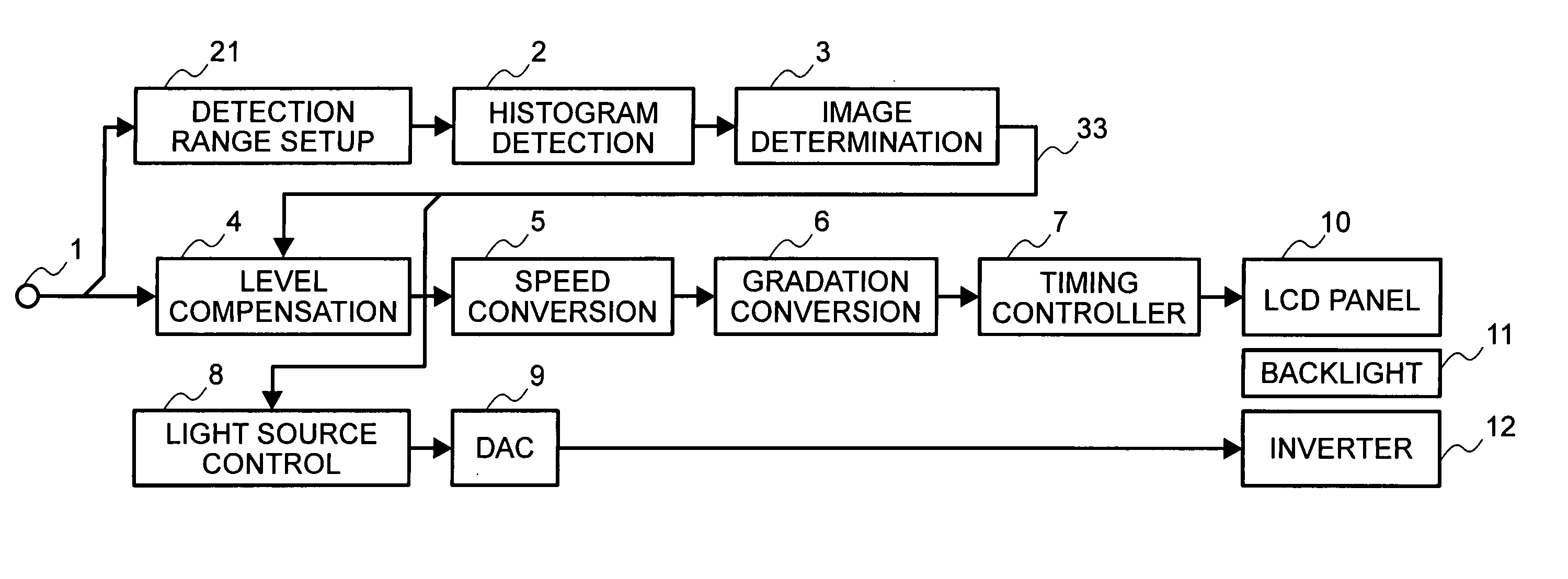
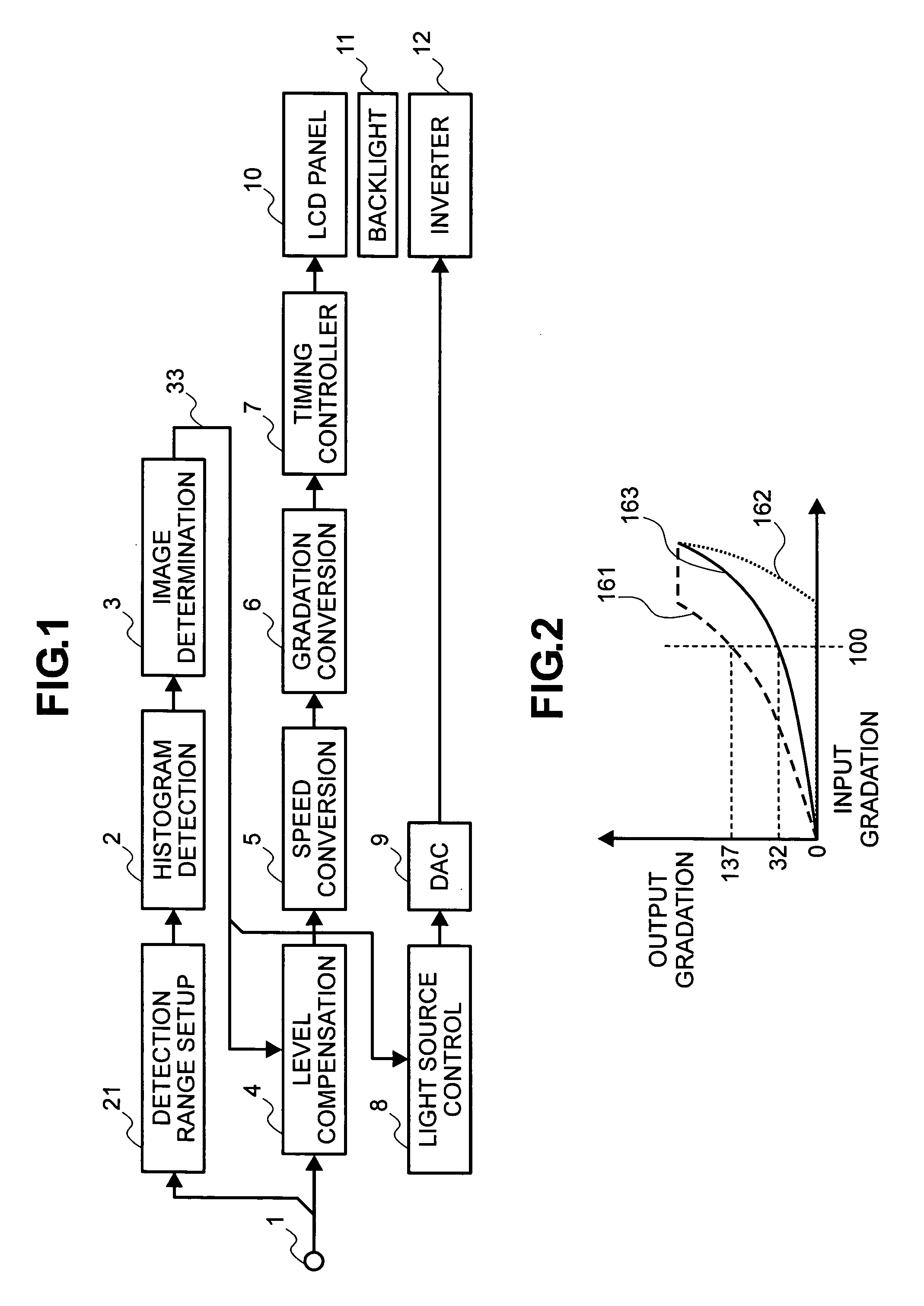
[0034]FIG. 1 is a block diagram for showing an example of the structures of a first embodiment, an image displaying apparatus according to the present invention. In the present embodiment, it is assumed that an image signal of a component format (YcbCr format) having a frame frequency of 60 Hz is inputted from an input terminal 1. The image signal inputted at the input terminal 1 is supplied to a level compensation portion 4. And, that image signal inputted is also supplied to a histogram detection portion 2 through a detection range setup portion 21. The detection range setup portion 21 is provided for setting up the range of brightness histogram, which is detected by the histogram detection portion, within one (1) piece of screen of the image (the details of which will be mentioned later). The histogram detection portion 2 detects the brightness histogram during a period of one (1) frame or one (1) field, for example, from a brightness signal (Y) included within the image signal i...

embodiment 2

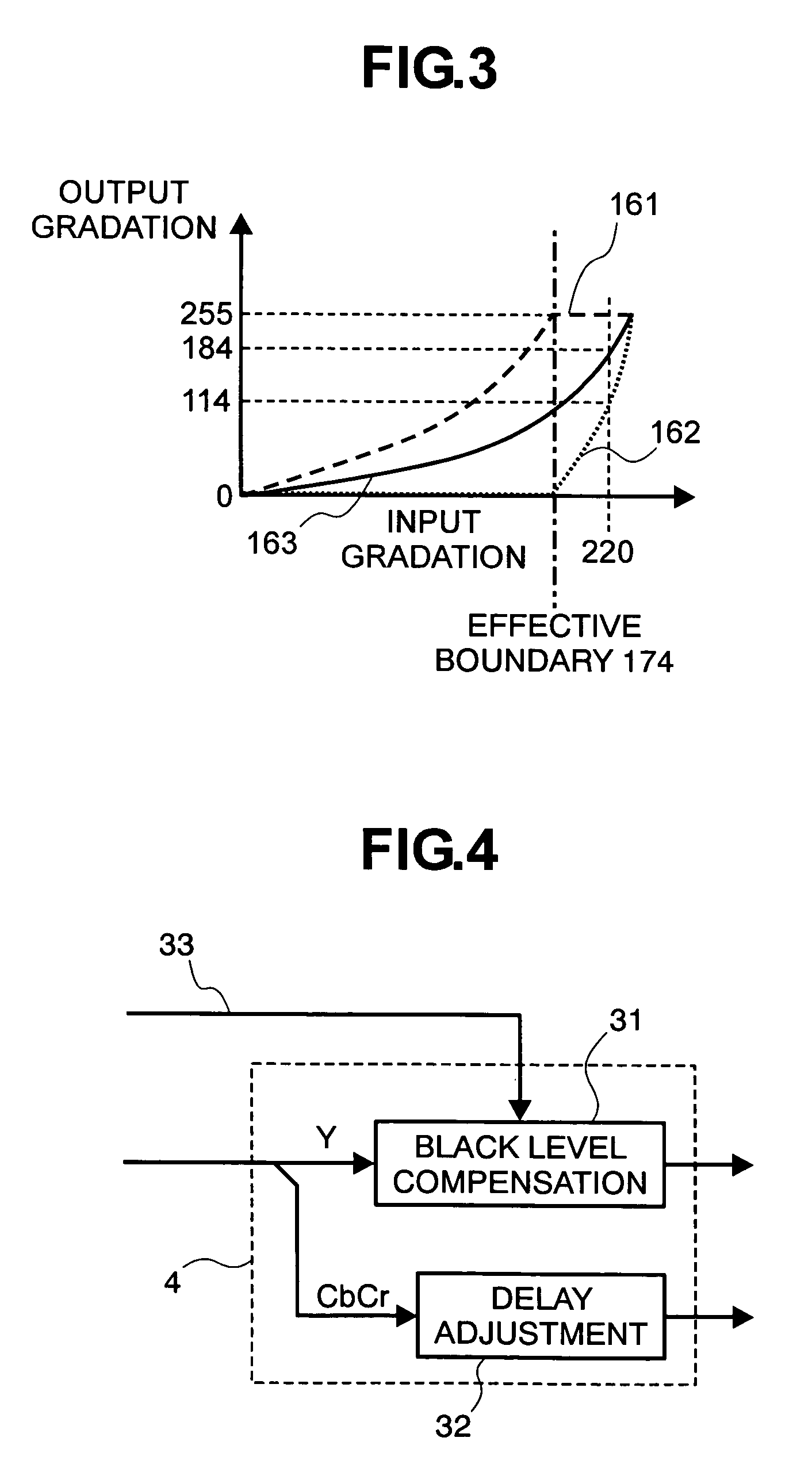
[0058] Next, explanation will be made on a second embodiment according to the present invention. The present embodiment is characterized by the following aspect, as will be shown in FIG. 8, that a gradation compensation portion 121 is newly provided within the level compensation portion 4, and thereby controlling the gradation compensation portion 121 with using a control signal 122. The structures other than the level compensation circuit 4 are same to that of the first embodiment. Hereinafter, explanation will be given on the details of the present embodiment. However, in FIG. 8, the constituent elements, being similar to those shown in FIG. 4, are given by the same reference numerals, to be omitted from the explanation thereof.

[0059] The present embodiment is provided for the purpose of lightening the black defacing caused due to the compensation of black level, which is conducted within the black level compensation portion 31, in particular, in case when amplitude of the input ...

embodiment 3

[0065] Next, explanation will be made about a third embodiment of the present invention. FIG. 12 is a block diagram for showing an example of the structures of the image displaying apparatus, according to the third embodiment of the present invention. In this figure, the constituent elements similar or same to those of the first embodiment shown in FIG. 1 are attached with the same reference numerals, and thereby being omitted from the detailed explanations thereof.

[0066] The present embodiment is provided for suppressing the flicker and / or motion judder in case when conducting the signal processing in accordance with the gradation distributing method mentioned above, in particular, upon the image signal, which is processed with the 2-3 pull-down or the 2-2 dull-down, such as, movie, CG or animation, for example, (hereinafter, being called by a “pull-down signal”, collectively), as the input image. Before giving explanation about the present embodiment, a reason will be explained, ...


PUM


Abstract

An image displaying apparatus, for improving motion blur, in particular, on an image displaying apparatus of hold-type, such as, a liquid crystal display element, etc., comprising: sub-frame producing portions (5, 6) for producing a first sub-frame, a second sub-frame being lower in the gradation than the first sub-frame, from an image of one (1) frame of an image signal inputted; a histogram detection portion (2) for detecting brightness histogram of the image signal; an image determination portion (3) for determining on whether the image signal inputted is a high-gradation image or not, from that brightness histogram; and a level compensation portion (4) for lowering a gradation level of that image signal inputted. And, according to the present invention, lowering the gradation of the high-gradation image keeps the difference in brightness between the first and the second sub-frames, and thereby increasing an effect of improving the motion blur.

Description

BACKGROUND OF THE INVENTION [0001] (1) Filed of the Invention [0002] The present invention relates to an image displaying apparatus, using a hold-type display element therein, such as, a liquid crystal display element or the like, for example. [0003] (2) Description of the Related Art [0004] Differing from an impulse-type, such as, a CRT, the hold-type display element, for example, a liquid crystal display element holds video data for each of pixels, during term of one (1) frame. For this reason, in case when displaying a moving picture on such the display element, a phenomenon of becoming dim on the contour or outline of an image (hereinafter, being called by “motion blur”) is generated, and this is visually recognized as an afterimage or incidental image for a user. [0005] The technology for improving such motion blur is already known, for example, in Japanese Patent Laying-Open No. 2005-173573 (2005). Thus, in the column [0102] of the Japanese Patent Laying-Open No. 2005-173573 b...

Claims


Application Information

Patent Timeline
IPC IPC(8): G09G3/36
CPCG09G3/2025G09G3/3406G09G3/3611G09G2310/061G09G2320/0261G09G2320/0271G09G2320/0633G09G2320/064G09G2320/0646G09G2340/0435G09G2360/16
Inventor OGINO, MASAHIROKABUTO, NOBUAKIONO, KIKUOMORI, IKUKOOOISHI, YOSHIHISA
Owner HITACHI DISPLAYS
Why Eureka
Try Eureka