
Light-emitting diode apparatus and control method thereof

a technology of light-emitting diodes and control methods, which is applied in the direction of instruments, static indicating devices, etc., can solve the problems of display motion blur, and achieve the effect of reducing the motion blur of the light-emitting diodes

Active Publication Date: 2021-10-12
AU OPTRONICS CORP
View PDF18 Cites 0 Cited by
  • Summary
  • Abstract
  • Description
  • Claims
  • Application Information

AI Technical Summary

Benefits of technology

[0005]The invention provides a light-emitting diode apparatus and a control method of the light-emitting diode apparatus that can improve the motion blur.
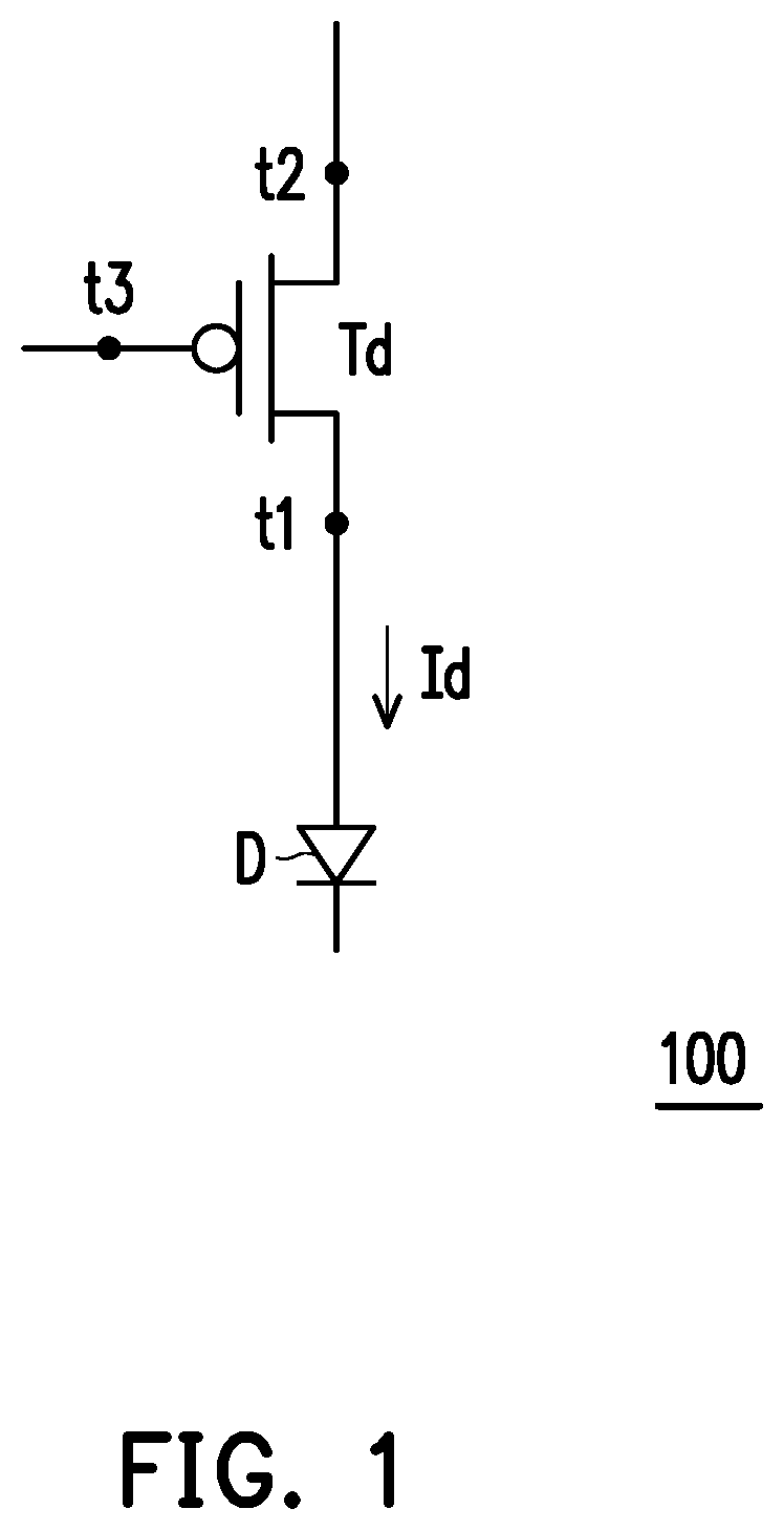
[0017]The light-emitting diode apparatus of the invention includes a driving transistor and a light-emitting diode. An anode and a cathode of the light-emitting diode are respectively coupled to a first terminal of the driving transistor and a low voltage source. A second terminal of the driving transistor is coupled to a high voltage source. A control terminal of the driving transistor receives a pre-reset voltage in a pre-resetting stage to be pre-reset. The control terminal of the driving transistor receives a reset voltage in a first resetting stage to be reset. The control terminal of the driving transistor is compensated to a compensation voltage in a compensation stage. The driving transistor provides a driving current in a light emission stage to drive the light-emitting diode to emit light. The pre-reset voltage increases a voltage difference between the control terminal and the first terminal of the driving transistor.
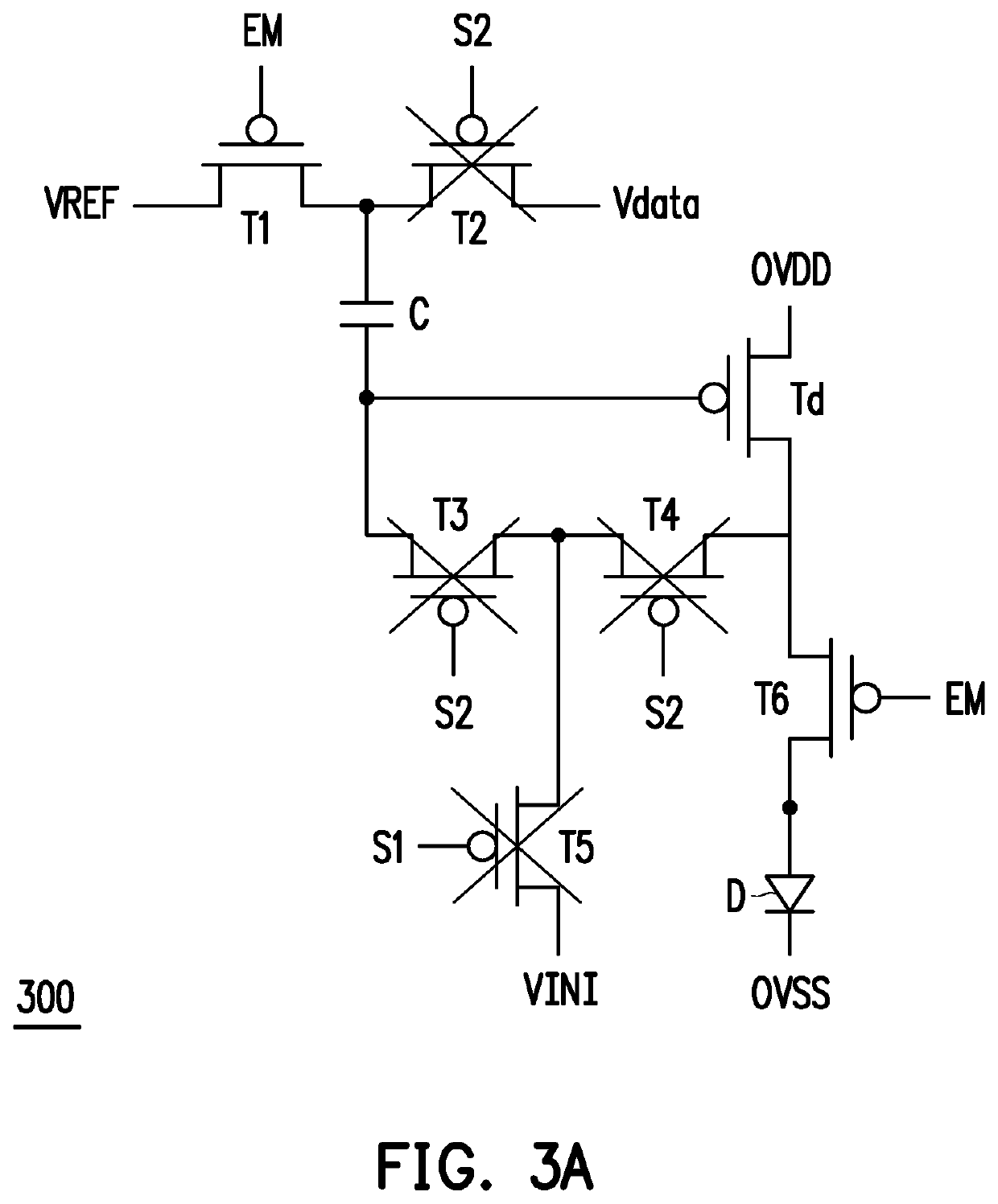
[0028]In light of the above, in the light-emitting diode apparatus of the invention, the control terminal of the driving transistor is pre-reset in the pre-resetting stage, the control terminal of the driving transistor is reset by using the reset voltage source in the first resetting stage, and the control terminal of the driving transistor is compensated to the compensation voltage in the compensation stage. Accordingly, by pulling down the voltage of the control terminal of the driving transistor in the pre-resetting stage and the first resetting stage, the voltage difference between the source and the gate of the driving transistor can be effectively increased to offset the coupling effect in the circuit, and motion blur of the light-emitting diode apparatus can be reduced.

Problems solved by technology

When the AMOLED is operated at a high speed, motion blur may be generated in the display.

Method used


Image

  • Light-emitting diode apparatus and control method thereof
  • Light-emitting diode apparatus and control method thereof
  • Light-emitting diode apparatus and control method thereof

Examples


Embodiment Construction

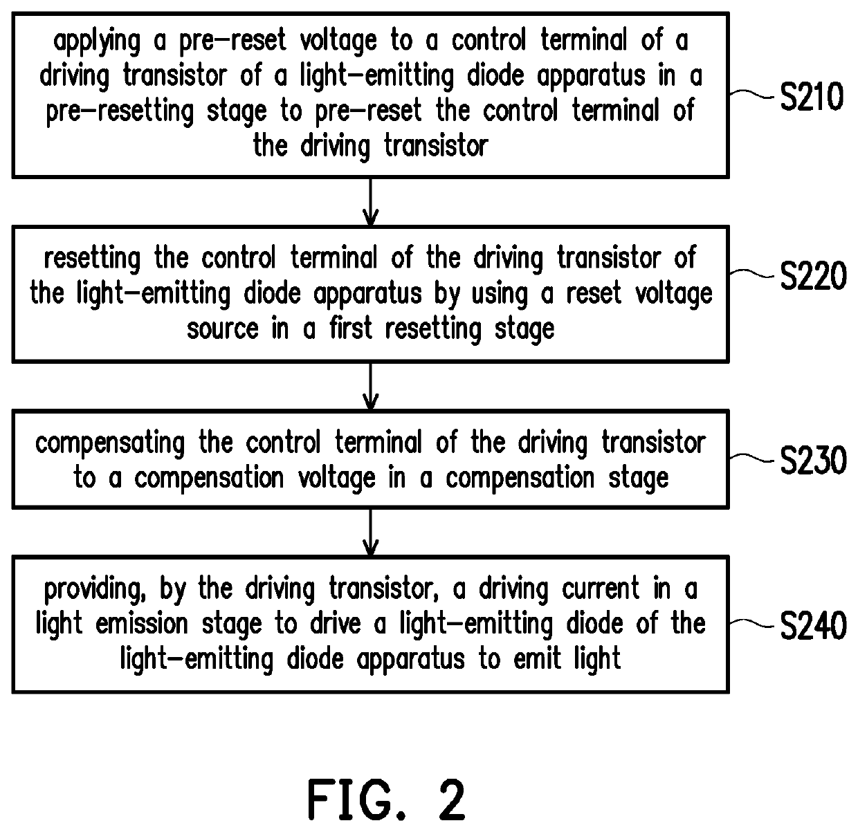
[0037]FIG. 1 is a schematic diagram illustrating coupling between a light-emitting diode and a driving transistor according to an embodiment of the invention. FIG. 2 is a flowchart illustrating a control method of a light-emitting diode apparatus according to an embodiment of the invention. Referring to both FIG. 1 and FIG. 2, in the embodiment of FIG. 1 and FIG. 2, a driving transistor Td includes a first terminal t1, a second terminal t2, and a control terminal t3. An anode of a light-emitting diode D is coupled to the first terminal t1 of the driving transistor Td.

[0038]In the present embodiment, the control method may include the following steps. In step S210, a pre-reset voltage is applied to the control terminal t3 of the driving transistor Td of a light-emitting diode apparatus 100 in a pre-resetting stage to pre-reset the control terminal t3 of the driving transistor Td. Specifically, the pre-reset voltage may be provided, for example, by coupling to the control terminal of ...


PUM

PropertyMeasurementUnit
voltage levelaaaaaaaaaa
voltageaaaaaaaaaa
voltageaaaaaaaaaa

Abstract

A light-emitting diode apparatus and a control method of the light-emitting diode apparatus are provided. The control method includes: applying a pre-reset voltage to a control terminal of a driving transistor of the light-emitting diode apparatus in a pre-resetting stage to pre-reset the control terminal of the driving transistor; resetting the control terminal of the driving transistor of the light-emitting diode apparatus by using a reset voltage source in a first resetting stage; compensating the control terminal of the driving transistor to a compensation voltage in a compensation stage; and providing, by the driving transistor, a driving current in a light emission stage to drive a light-emitting diode of the light-emitting diode apparatus to emit light.

Description

CROSS-REFERENCE TO RELATED APPLICATION[0001]This application claims the priority benefit of Taiwan application serial no. 107119932, filed on Jun. 8, 2018. The entirety of the above-mentioned patent application is hereby incorporated by reference herein and made a part of this specification.BACKGROUND OF THE INVENTIONField of the Invention[0002]The disclosure relates to a light-emitting diode apparatus and a control method of the light-emitting diode apparatus.Description of Related Art[0003]As display technologies advance, the light-emitting diode has been applied to various display techniques, and the active-matrix organic light-emitting diode (AMOLED) is one of the main areas of development for the display techniques.SUMMARY OF THE INVENTION[0004]When the AMOLED is operated at a high speed, motion blur may be generated in the display.[0005]The invention provides a light-emitting diode apparatus and a control method of the light-emitting diode apparatus that can improve the motion...

Claims


Application Information

Patent Timeline
Patent Type & Authority Patents(United States)
IPC IPC(8): G09G3/3233G09G3/3258G09G3/3225G09G3/325G09G3/3208G09G3/32
CPCG09G3/3233G09G3/325G09G3/3208G09G3/3225G09G3/3258G09G3/32G09G2300/043G09G2300/0842G09G2300/0861G09G2320/0261
Inventor HUNG, SEN-CHUANKUO, SHIH-HAO
Owner AU OPTRONICS CORP
Learn More