Apparatus for collecting and calculating quantity of patient fluid loss and method of using same

a technology for patient fluid loss and apparatus, applied in the field of apparatus for collecting and calculating patient fluid loss and the method of using same, can solve the problems of time-consuming manual measurement of fluid volume, raising the risk of false reading, and subjecting nurses to technical and visual inaccuracy, so as to achieve accurate electronic sensing of fluid mass

Inactive Publication Date: 2007-05-10
HAMA YOSHITO
View PDF19 Cites 26 Cited by
  • Summary
  • Abstract
  • Description
  • Claims
  • Application Information

AI Technical Summary

Benefits of technology

The present invention provides an improved device that can accurately measure the weight of fluids being collected. It includes a support table with a hole designed to hold a hook or hanger carrying the container. This allows the fluid to be collected while remaining stable during measurement. Overall, this technology ensures precise results when measuring the volume of liquids.

Problems solved by technology

The technical problem addressed in this patent text is the need for a better way to measure bodily fluids, especially in critically ill or recovered patients. Current methods involve manually checking the amount of fluid in a container through a transparent window, but this process is slow, inconsistent, and potentially unsafe due to the possibility of touching the fluid. There is a need for a completely automated system that uses advanced technology to measure the weight of the fluid without manipulating the bag or taking risky steps.

Method used


Image

  • Apparatus for collecting and calculating quantity of patient fluid loss and method of using same
  • Apparatus for collecting and calculating quantity of patient fluid loss and method of using same
  • Apparatus for collecting and calculating quantity of patient fluid loss and method of using same

Examples


Embodiment Construction

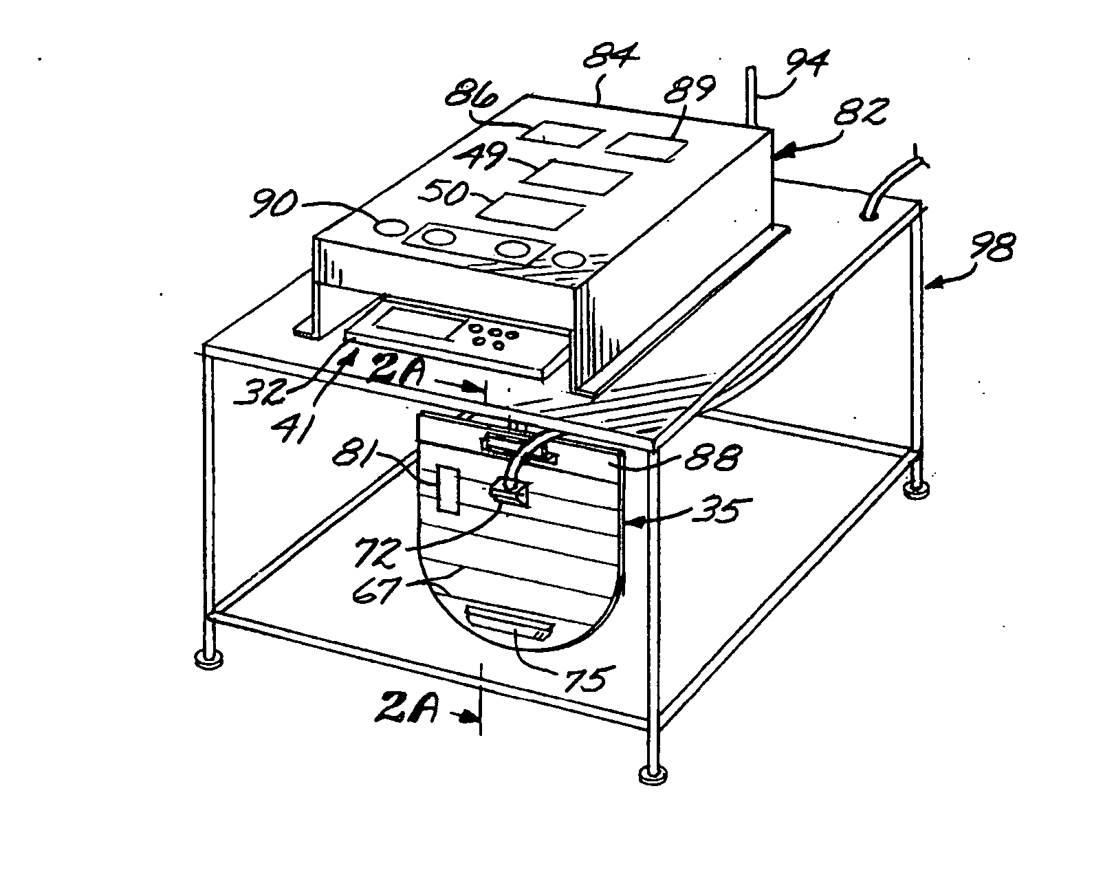
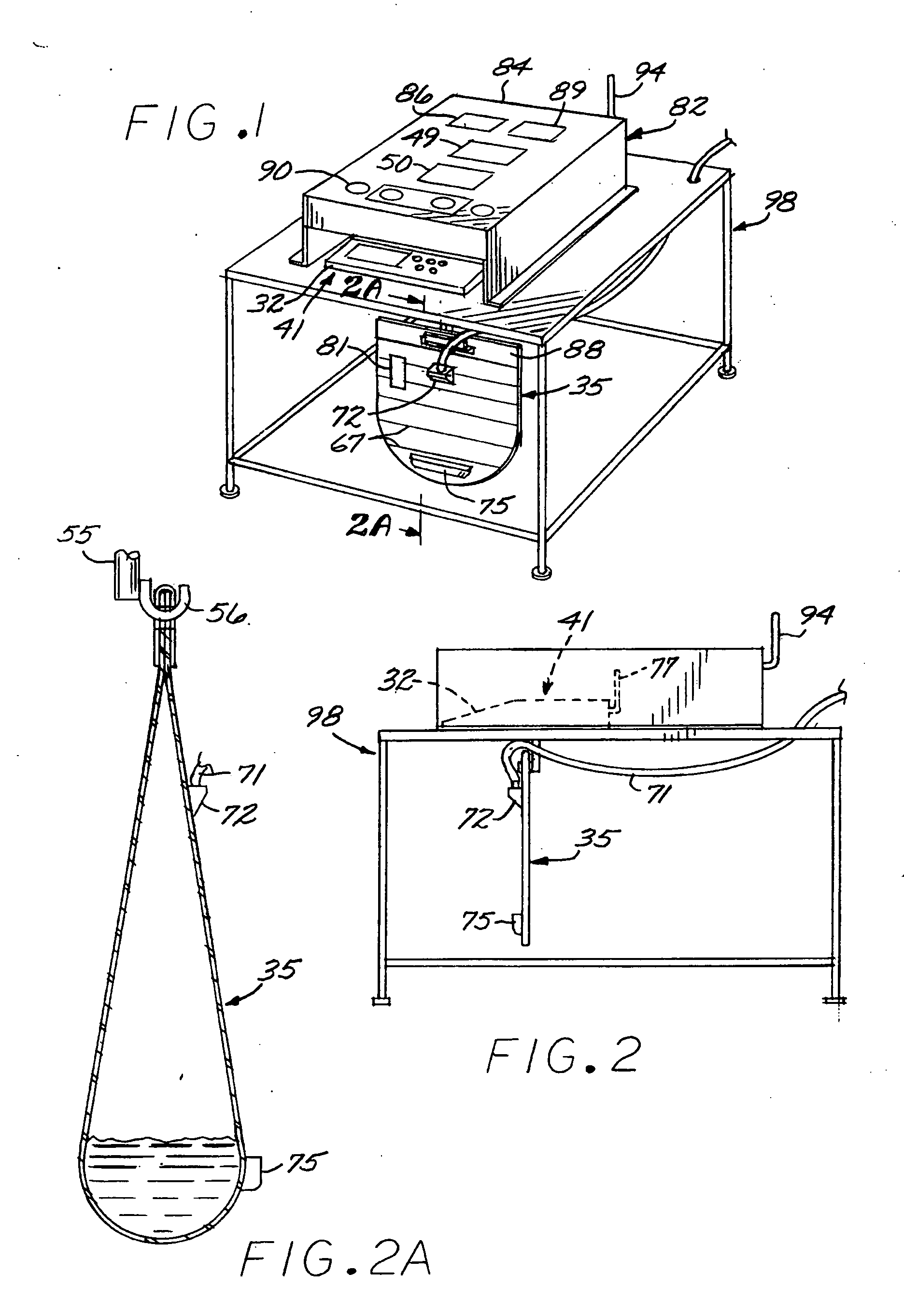
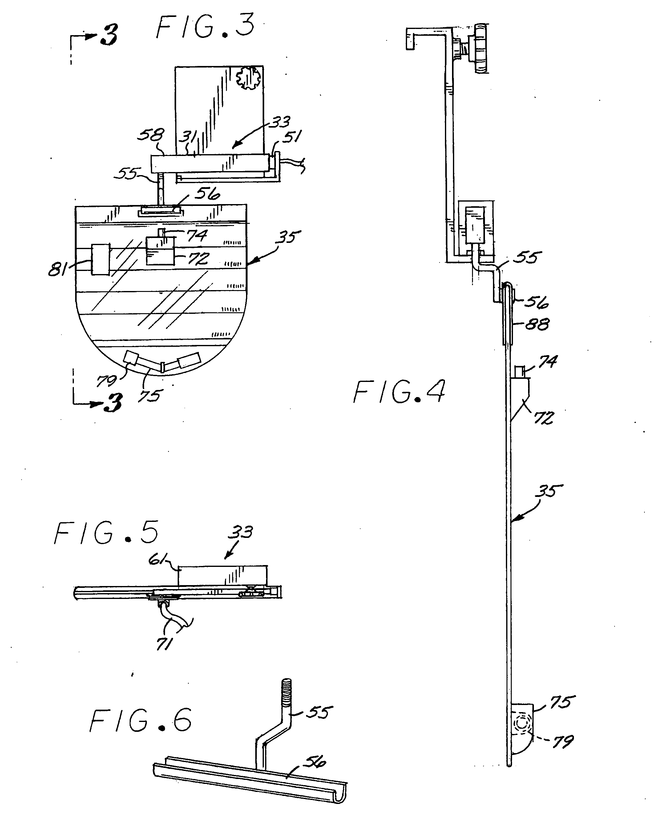
[0032] Referring to FIGS. 1 and 7, the body fluid collection and monitoring system of the present invention includes, generally, a control unit 41 connected with a load cell weight meter 33 in the form of a cantilever flexible beam 51 housed in a housing 31 and suspending from the free end thereof a fluid collection bag 35 having a laterally distended rounded bottom wall 37 configured symmetrical about a vertical centerline 59. Referring to FIG. 9, the control unit includes a converter 45 responsive to a signal from the weight sensor 33 and data from a memory 47 to generate an output signal which may be communicated to a display panel 49 (FIG. 12) to display an output corresponding with the weight calculated as being representative of the volume of fluid collected in the container bag 35.

[0033] The housing 31 may take many different forms and may, for instance, be in the form of an open frame to suspend a hanger 55. It is necessary that the weight scale provide quick response and a...


PUM


Abstract

A monitoring system including a control unit having a weight scale for carrying a collection bag configured with a bottom wall distended in a rounded concave shape, the central unit being responsive to the amount of fluid collected to produce a read-out which may be recorded or observed by a technician. In one embodiment, the system includes a hook suspended from the weight scale and projecting downwardly through a slot in a bottom wall to hook to the container.

Description


Claims


Application Information

Patent Timeline
Owner HAMA YOSHITO
Why Eureka
Try Eureka