Thin film probe card

a probe card and thin film technology, applied in the direction of electrical testing, measurement devices, instruments, etc., can solve the problems of shortening poor conductive contact with the wires, and broken probes, so as to reduce the pressure exerted on the probe card and extend the life of the probe card

Inactive Publication Date: 2007-05-17
WINTEK CORP
View PDF10 Cites 1 Cited by
  • Summary
  • Abstract
  • Description
  • Claims
  • Application Information

AI Technical Summary

Benefits of technology

[0007] The primary objective of the present invention is to provide a thin film probe card, which may reduce the pressure exerted on the probes when the probes contact the testing panel to protect the probe and extend the life of the probe card.

Problems solved by technology

The worn or broken probes 4 have a poor conductive contact with the wires 6a that is bad for the testing and shorts the life of the probe card 1.
It affects the accuracy of the testing and may damage the testing panels also.

Method used


Image

  • Thin film probe card
  • Thin film probe card
  • Thin film probe card

Examples


Embodiment Construction

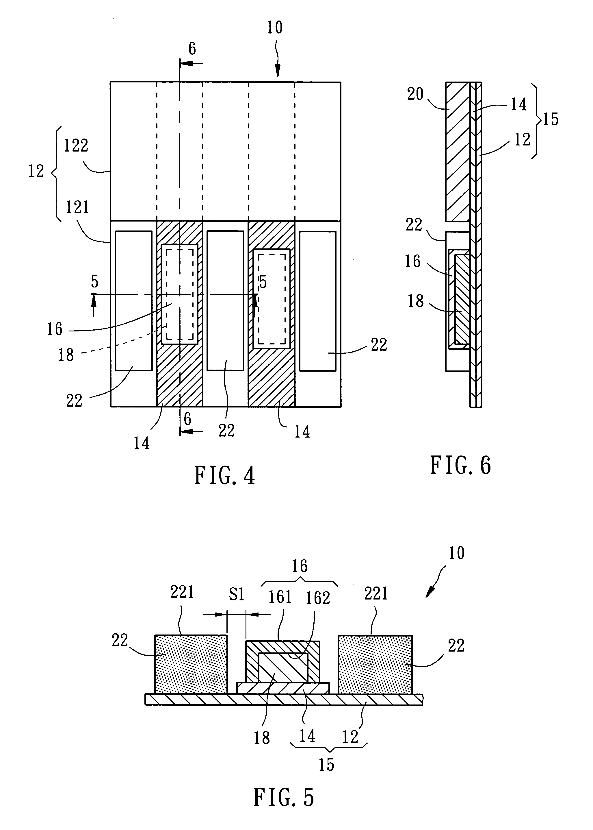
[0031]FIG. 4 to FIG. 6 show a probe card 10 of the first preferred embodiment of the present invention, which is used in test of a circuit of a testing device. FIG. 7 shows the probe card 1 of the present invention is conductively connected to a liquid crystal panel 100 for testing.

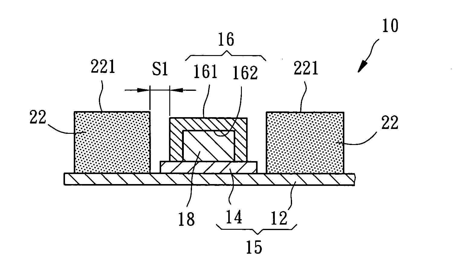
[0032] The probe card 10 of the first preferred embodiment of the present invention includes a substrate 15 with a plate 12 and a plurality of wires 14 on the plate 12, a plurality of probes 16, a plurality of conductive members 18, an insulating film 20 and a plurality of first elastic members.

[0033] The plate 12 has a contacting portion 121 and a non-contacting portion 122.

[0034] The wires 14 are extended on both of the contacting portion 121 and the non-contacting portion 122 in parallel, which transfer electric signals in the test.

[0035] The probes 16 are conductive foils made of nickel or nickel alloy. Each of the wires 14 on the contacting portion 121 of the plate 12 includes one or more probes ...


PUM


Abstract

A thin film probe card includes a plate and a plurality of wires on the plate, each of which is electrically connected with at least a thin film probe. A plurality of elastic members are provided between the probes, which absorbs the force of the probes in the test to protect the probes from wear and extend the product life of the probe card.

Description

BACKGROUND OF THE INVENTION [0001] 1. Field of the Invention [0002] The present invention relates generally to a testing device of electric circuit, and more particularly to a thin film probe card with flexible buffer device. [0003] 2. Description of the Related Art [0004]FIG. 1 and FIG. 2 show a conventional thin film probe card 1 for testing of optical display panels, such as liquid crystal display. The probe card 1 includes a plate 2, a plurality of wires 3, a plurality of probes 4 and an insulating film 5. The plate 2 has a contacting portion 2a and a non-contacting portion 2b. Each of the wires 3 is associated with conductive wires 6a of a testing panel 6 (FIG. 3) respectively. The probes 4 are made of conductive metal foils to cover the wires 3 on the contacting portion 2a. The insulating film 5 covers the cover the wires 3 on the non-contacting portion 2. [0005] As shown in FIG. 3, the probes 4 of the probe card 1 contact the conductive wires 6a, such as ITO conductive film, ...

Claims


Application Information

Patent Timeline
Patent Type & Authority Applications(United States)
IPC IPC(8): G01R31/02
CPCG01R31/2889G09G3/006
Inventor WANG, CHIH-YUANCHANG, HENG-YI
Owner WINTEK CORP
Why Eureka
Try Eureka