
Test method and device for land grid array components

a technology of land grid array and component, applied in the direction of measurement device, electrical testing, instruments, etc., can solve the problems of easy damage, high cost of probe, easy damage to test objects, etc., to avoid damage to test objects under pressure, improve contact performance, and reduce the pressure exerted by fixtures

Inactive Publication Date: 2009-11-19
UNIVERSAL SCI IND CO LTD
View PDF5 Cites 3 Cited by
  • Summary
  • Abstract
  • Description
  • Claims
  • Application Information

AI Technical Summary

Benefits of technology

[0007]The object of the present invention is to provide a test method and device for Land Grid Array components which can improve contact performance and reduce pressure exerted by a fixture, thereby avoiding damaging a test object under pressure.
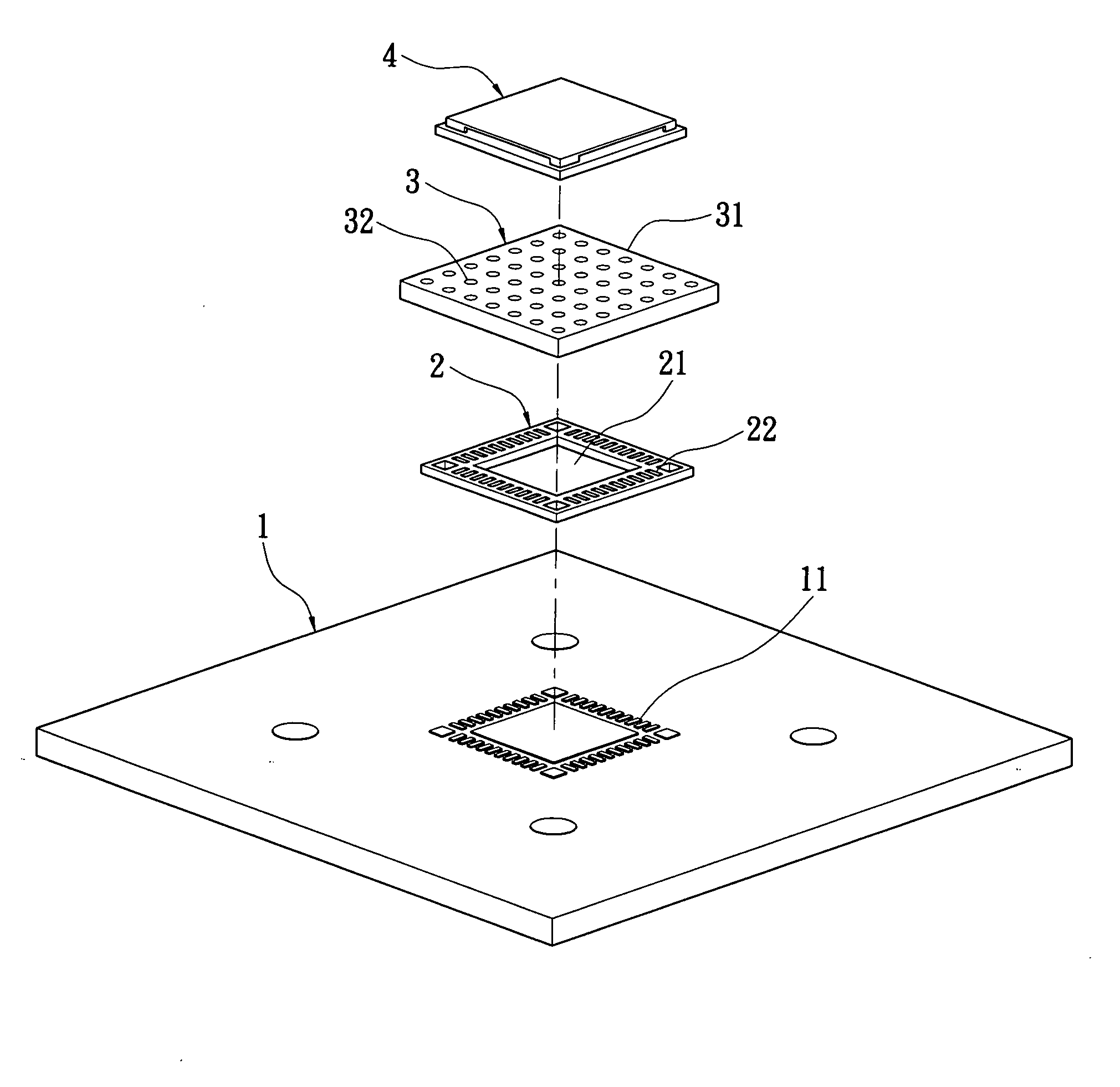
[0010]The present invention is advantageous that the secondary test board of the present invention brings a drop to the test board so that the pressure on the conducting spacer can be concentrated on the conducting terminals of the test object, thereby improving contact performance, reducing pressure exerted by a fixture, and avoiding damaging the test object under pressure.

Problems solved by technology

Though the probes have good contact performance, they are easily damaged and need to be replaced frequently.
Besides, the probes have high cost.
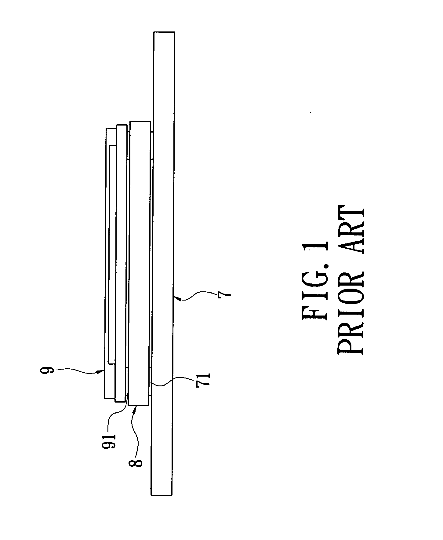
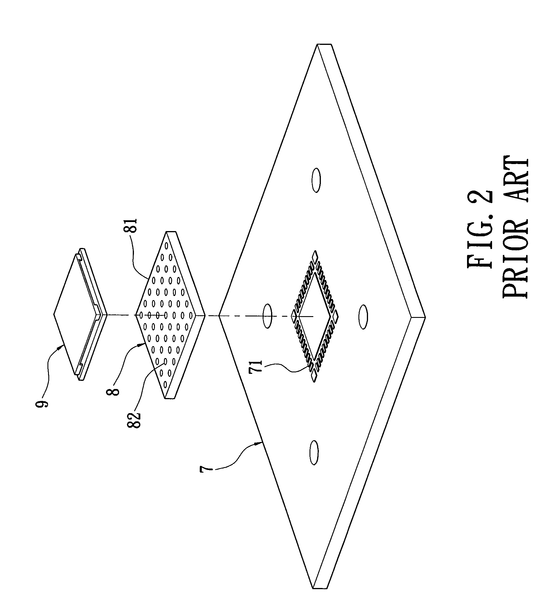
The conducting spacers have lower cost than the probes and aren't damaged easily, but they have bad contact with the test objects with flat surfaces so that it is necessary to exert large forces on the test objects to test.
If the test object 9 has a ceramics substrate, it tends to be damaged under pressure.

Method used


Image

  • Test method and device for land grid array components
  • Test method and device for land grid array components
  • Test method and device for land grid array components

Examples


Embodiment Construction

[0018]Please refer to FIGS. 3-5, the present invention provides a test method for Land Grid Array components, and more especially provides a test method for an electronic part (a test object) with Land Grid Array components. The method includes the steps of:

[0019](1) Firstly, providing a test board 1 which has a plurality of test points 11 on a top surface thereof, corresponding to a plurality of conducting terminals 41 on a bottom surface of the test object 4.

[0020](2) Providing a secondary test board 2 which has a quadrate hollow-out portion 21 thereinside and a plurality of conductors 22 around the hollow-out portion 21 thereon, wherein the hollow-out portion 21 extends through the secondary test board 2 from a top surface to a bottom surface, and the plurality of conductors 22 correspond to the plurality of test points 11 and extend through the secondary test board 2 from the top surface to the bottom surface. In the embodiment, the secondary test board 2 forms the hollow-out po...


PUM


Abstract

A test method for Land Grid Array components includes the steps of: providing a test board with a plurality of test points; providing a secondary test board which has a plurality of conductors extending therethrough from a top surface to a bottom surface and forms a drop thereon, placing the secondary test board on the test board and contacting the conductors with the test points correspondingly; disposing a conducting spacer on the secondary test board, which is contacted with the conductors of the secondary test board correspondingly; and placing a test object on the conducting spacer, which has a plurality of conducting terminals contacted with the conducting spacer, and pressing the test object downwards so that the conducting terminals, the conducting spacer, the conductors and the test points are electrically connected for testing the test object. A test device for Land Grid Array components also is provided.

Description

BACKGROUND OF THE INVENTION[0001]1. Field of the Invention[0002]The present invention relates to a test method and device, and more especially to a test method and device for electronic parts with Land Grid Array (LGA) components.[0003]2. Description of Related Art[0004]Most of conventional test fixtures for SMT parts (test objects) with LGA components are electrically connected to the test objects and test boards via probes or conducting spacers. Though the probes have good contact performance, they are easily damaged and need to be replaced frequently. Besides, the probes have high cost. The conducting spacers have lower cost than the probes and aren't damaged easily, but they have bad contact with the test objects with flat surfaces so that it is necessary to exert large forces on the test objects to test.[0005]Please refer to FIG. 1 and FIG. 2, a prior test device with a conducting spacer is disclosed. The test device disposes a conducting spacer 8 on a test board 7. The conduct...

Claims


Application Information

Patent Timeline
Patent Type & Authority Applications(United States)
IPC IPC(8): G01R31/02
CPCH05K7/1061G01R31/2889
Inventor LI, KUAN-HSING
Owner UNIVERSAL SCI IND CO LTD
Learn More