

Vapor chamber and supporting structure thereof
- Summary
- Abstract
- Description
- Claims
- Application Information
AI Technical Summary
Benefits of technology
Problems solved by technology
Method used
Image

Examples
Embodiment Construction
[0018]In cooperation with attached drawings, the technical contents and detailed description of the invention are described thereinafter according to a preferable embodiment, being not used to limit its executing scope. Any equivalent variation and modification made according to appended claims is all covered by the claims claimed by the present invention.
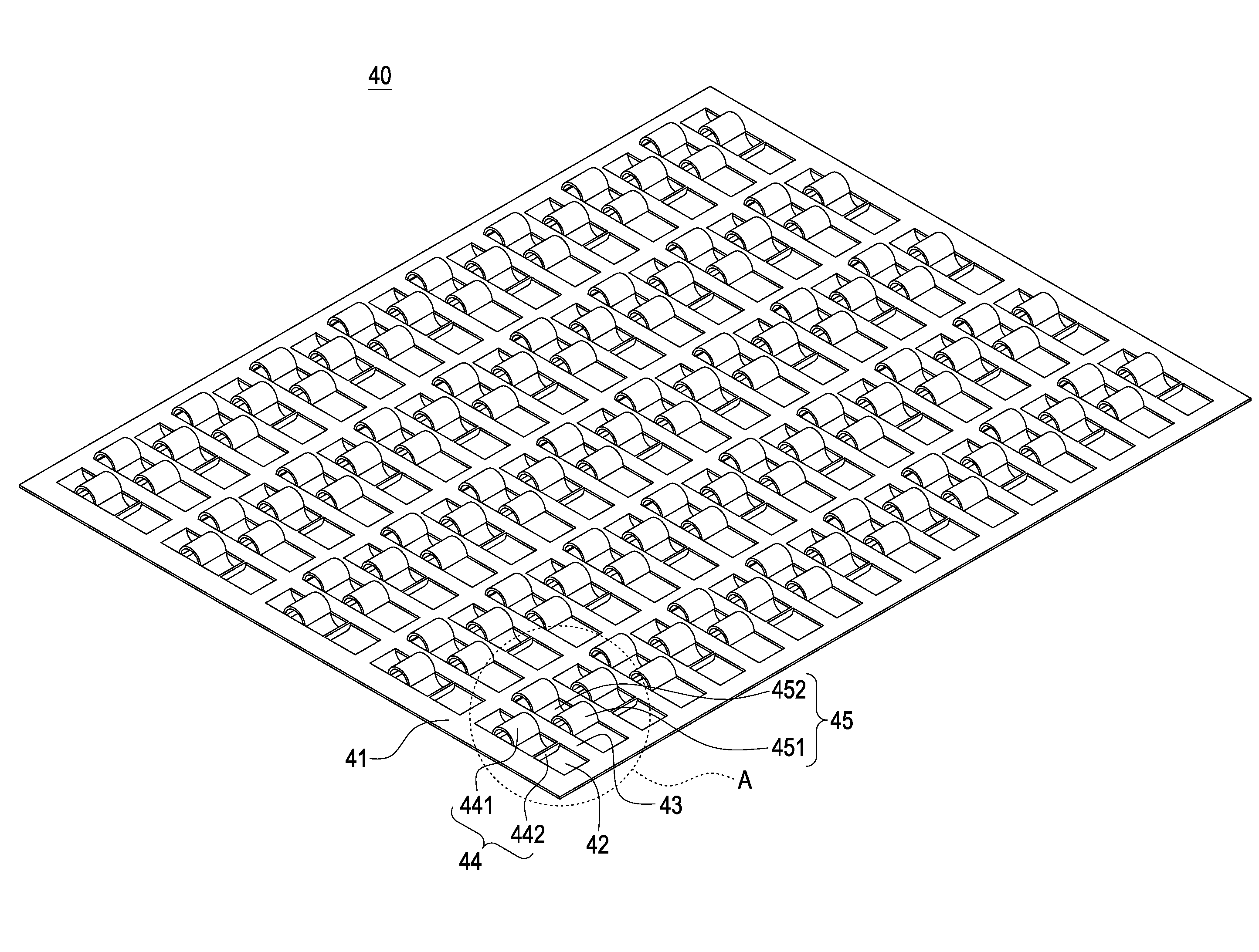
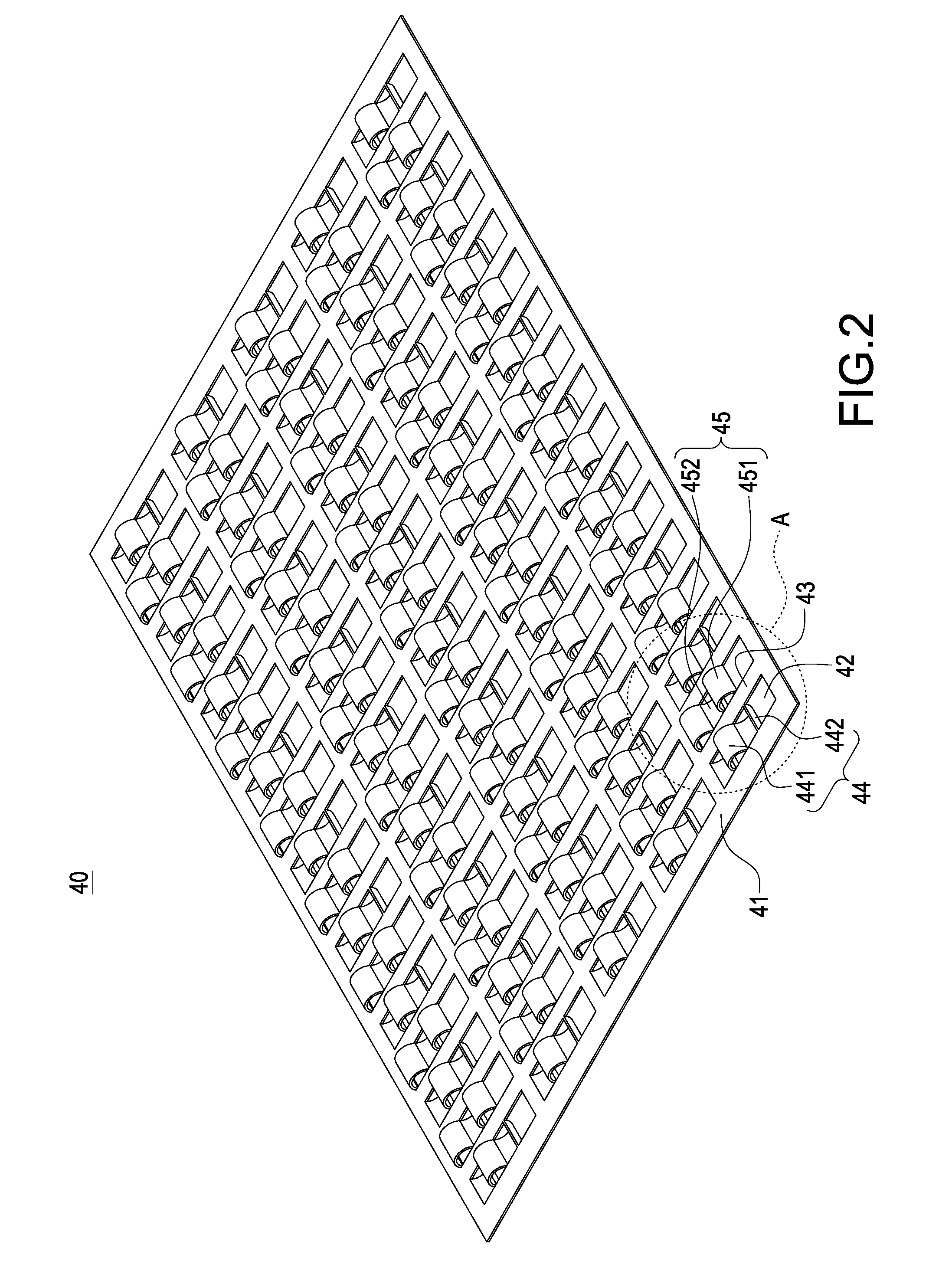
[0019]Please refer to FIG. 2 and FIG. 3, which respectively are a perspective outer appearance view of a supporting structure according to the present invention and a locally enlarging view of an “A” zone in FIG. 2. The invention is to provide a vapor chamber and a supporting structure thereof, in which the vapor chamber includes a casing 10, a working fluid (please refer to FIG. 6), a capillary wick (please refer to FIG. 4), and a supporting structure 40.
[0020]In this case, the supporting structure 40 includes a rectangular plate 41, which is made of metal materials with highly structural strength, and on which a plurality of chan...
PUM
 Abstract
Description
Claims
Application Information