Generating Electricity Using the Outfall of a Waste Water Treatment Plant

Inactive Publication Date: 2020-11-05
MCCLURKIN JR JOHN B
View PDF0 Cites 1 Cited by
  • Summary
  • Abstract
  • Description
  • Claims
  • Application Information

AI Technical Summary

Benefits of technology

[0004]The present invention uses the solid body effect, a property of non-compressible fluids such as water, to produce useful amounts of work that can be used to generate electricity. This novel approach increases the amount of work that can be done with the potential energy stored in the mass of the water flowing through the WWTP. One of the major obstacles the present invention overcomes is that in spite of there being a huge mass of water available from a WWTP, little actual work can be done with it because it is released over such a long period of time, in fact, most WWTPs are rated in gallons/day capa

Problems solved by technology

However, there are significant differences in the two processes, principally in

Method used


Image

  • Generating Electricity Using the Outfall of a Waste Water Treatment Plant

Examples


Example

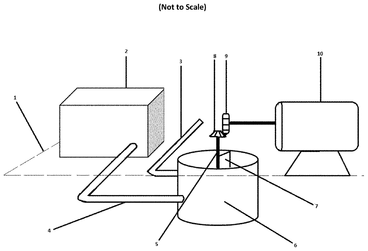
[0007]In the drawing, the dashed line 1 designates ground level. As can be seen in the drawing, in the preferred embodiment, the WWTP 2 and generator 10 are located on ground level, while the circular tank 6 is located mostly below ground level. This increases the downhill distance the water flows from the WWTP before entering the circular tank 6 thus increasing its head while at the same time allowing earth to be piled against the tank 6 reinforcing it against collapse. Water enters the circular tank 6 through the pipe 4 which acts as both the outlet for the WWTP 2 and the inlet for the tank 6. The inlet part of pipe 4 is aligned tangentially with the interior wall of the container to help impart rotation to the water in the tank 6. The inlet pipe 4 is sized based on the available volume of water to impart a velocity to the incoming water sufficient to induce rotation in the water in the tank as a whole. The outlet pipe 3 is located above the inlet. This means that only the top lay...


PUM


Abstract

Described is a process whereby the water discharged from a Waste Water Treatment Plant (WWTP) can be used to generate electricity.

Description

CLAIM OF PRIORITY[0001]The present application claims priority to and incorporates by reference U.S. Provisional Application No. 62 / 920,471 filed May 2, 2019 entitled “Generating Electricity Using the Outfall of a Waste Water Treatment Plant”BACKGROUND OF THE INVENTION[0002]The present disclosure generally relates to an electrical power generating system using flowing water as the principal energy source.[0003]The amount of energy available in falling water has attracted engineers looking for motive power since the beginning of the industrial revolution. Water has been used to generate electricity starting with the first days of electrical generation on an industrial scale. Most visible in large scale hydro projects marked by huge dams, micro hydro projects running in small streams and rivers have recently become more common as the search for clean, renewable energy is pursued. Recent innovations have included placing small generating turbines in municipal water lines to generate el...

Claims


Application Information

Patent Timeline
IPC IPC(8): F03B13/08H02K7/116H02K7/18
CPCH02K7/116F03B13/08H02K7/1823F03B13/00F05B2220/602F05B2260/4031F05B2260/5032Y02B10/50Y02E10/20Y02E10/72
Inventor MCCLURKIN, JR., JOHN B.
Owner MCCLURKIN JR JOHN B
Why Eureka
Try Eureka