
White organic electroluminescent elements and displays using the same

Active Publication Date: 2008-03-20
AU OPTRONICS CORP
View PDF16 Cites 5 Cited by
  • Summary
  • Abstract
  • Description
  • Claims
  • Application Information

AI Technical Summary

Benefits of technology

[0010]With a simple adjustment of the thickness of the light emitting layer of the white organic electroluminescent element, the present invention provides a white organic electroluminescent element that emits white light. The present invention increases the work window of the full color technology.

Problems solved by technology

Though the white organic electroluminescent element technology has been improved, there are still some technical problems needing to be resolved, wherein the complexity of element is one issue.

Method used


Image

  • White organic electroluminescent elements and displays using the same
  • White organic electroluminescent elements and displays using the same
  • White organic electroluminescent elements and displays using the same

Examples


first embodiment

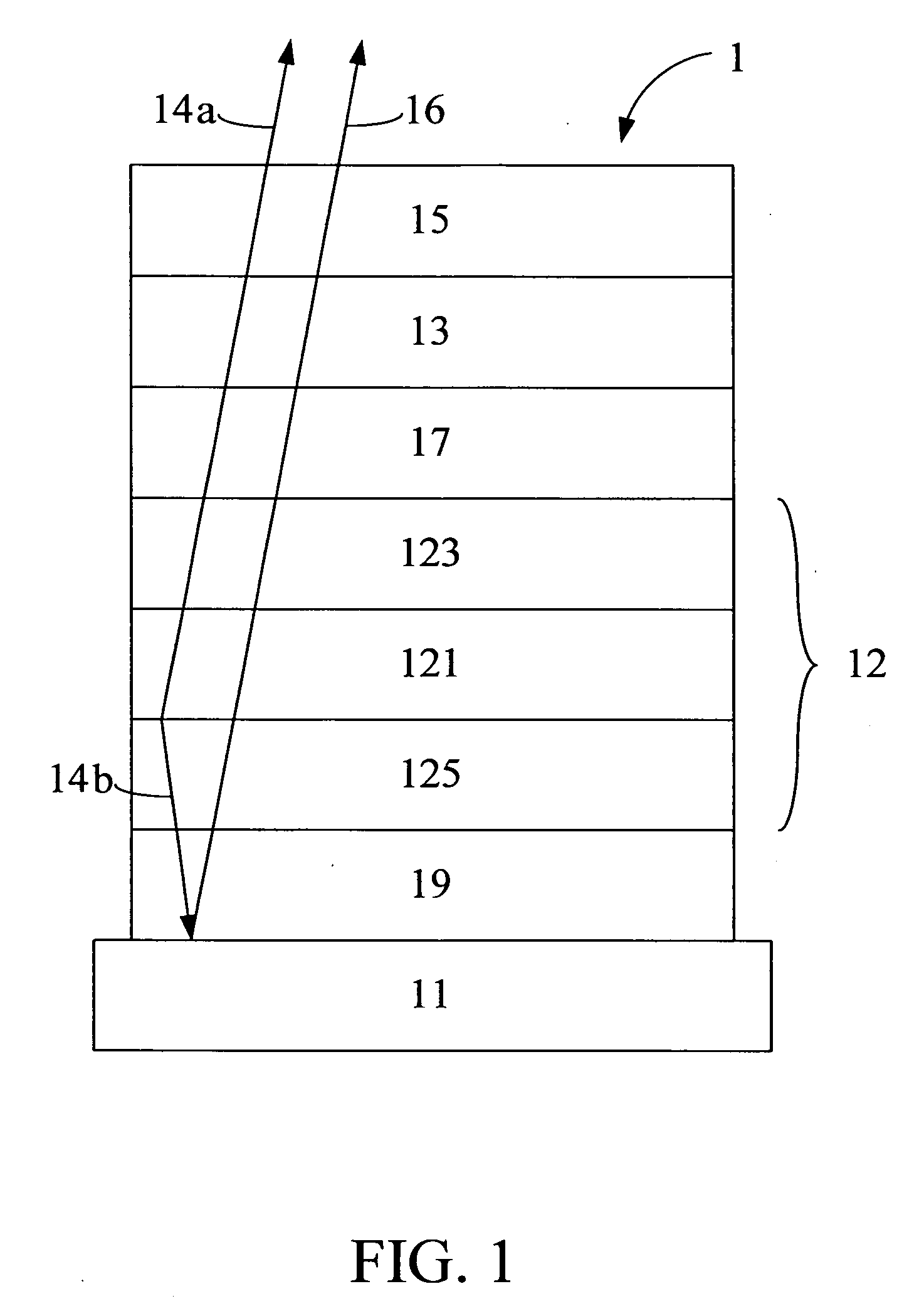
[0015]the present invention is a white organic electroluminescent element 1 as shown in FIG. 1. The white organic electroluminescent element 1 comprises an anode 11, a cathode 13, a capping layer 15, an electron injection layer (EIL) 17, a hole injection layer (HIL) 19, and an organic layer 12. The capping layer 15 is above the cathode 13, while the EIL 17, the HIL 19, and the organic layer 12 are disposed between the anode 11 and the cathode 13. The organic layer 12 is disposed between the EIL 17 and the HIL 19. The organic layer 12 comprises a blue light emitting layer 121, an electron transporting layer (ETL) 123 disposed between the blue light emitting layer 121 and the cathode 13, and a hole transporting layer (HTL) 125 disposed between the blue light emitting layer 121 and the anode 11.

[0016]In the white organic electroluminescent element 1 of the present invention, the anode 11 is disposed above a substrate. The anode not only serves as an electrode, but may also reflect ligh...

second embodiment

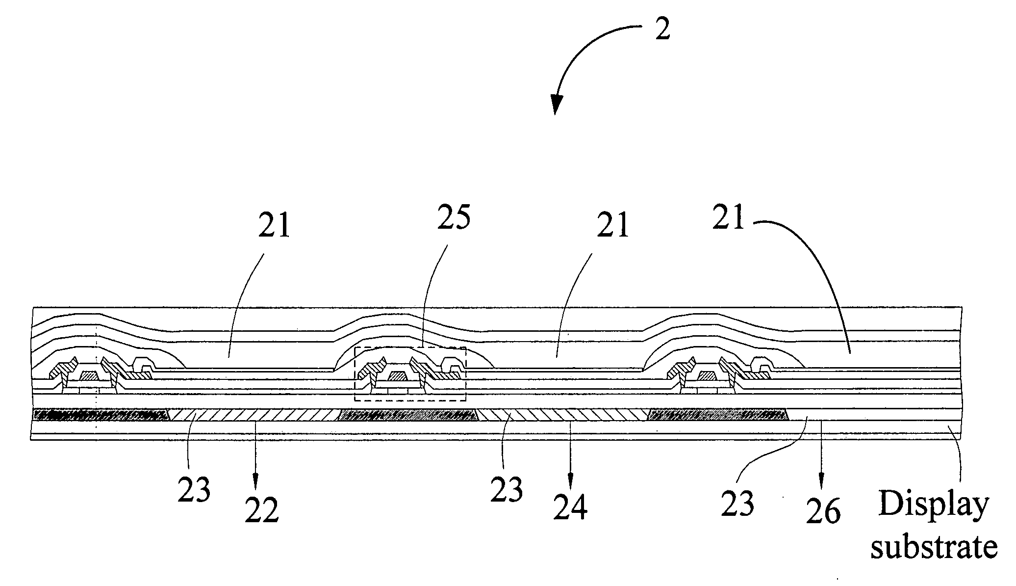
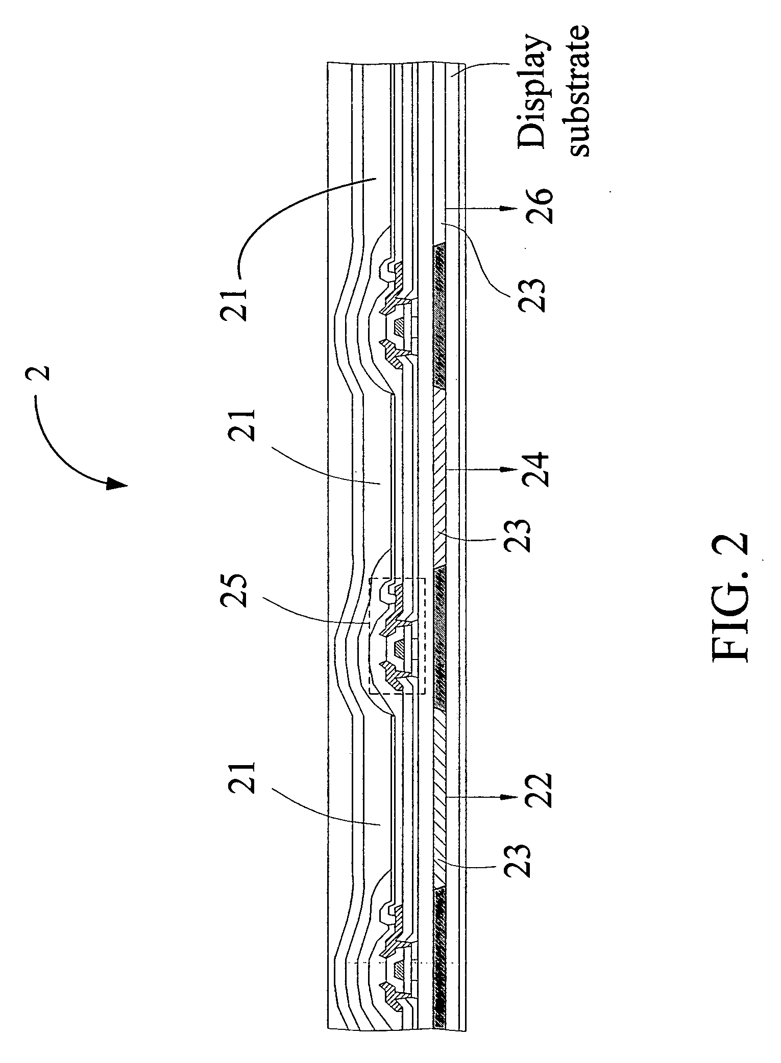
[0026]the present invention is an organic electroluminescent display 2, as shown in FIG. 2. The organic electroluminescent display 2 comprises the three aforementioned white organic electroluminescent elements 21, three color filters 23, and three corresponding driving circuits 25. The three color filter 23, corresponding to the three white organic electroluminescent elements, are configured to transfer the white lights emitted from the three white organic electroluminescent elements 21 to a first color beam 22, a second color beam 24, and a third color beam 26. The first color beam 22 is a red light, the second color beam 24 is a blue light, and the third color beam 26 is a green light. The three corresponding driving circuits 25 control the on or off states of the red light, the blue light, and the green light respectively for displaying different colors.

[0027]FIG. 3 is an exploded view of the aforementioned organic electroluminescent display 2. The organic electroluminescent disp...


PUM

PropertyMeasurementUnit
Thicknessaaaaaaaaaa
Thicknessaaaaaaaaaa
Thicknessaaaaaaaaaa

Abstract

A white organic electroluminescent element for an organic electroluminescent display and a display using the white organic electroluminescent are provided. The organic electroluminescent display comprises a white organic electroluminescent element and a color filter. The white organic electroluminescent element comprises an anode, a cathode, a capping layer, and an organic layer. The capping layer is disposed on the cathode. The organic layer is disposed between the anode and the cathode, and comprises a blue light emitting layer. The thickness of the organic layer is X+120N nm, wherein 85≦X≦125, and N=0, 1, or 2. The white organic electroluminescent element is configured to emit a white light. The color filter is configured to convert the white light to a first color beam, with the first color beam being either red, blue, or green.

Description

[0001]This application benefits from the priority of Taiwan Patent Application No. 095134438 filed on Sep. 18, 2006.BACKGROUND OF THE INVENTION[0002]1. Field of the Invention[0003]The present invention relates to a white organic electroluminescent element; in particular, the invention relates to a white organic electroluminescent element adapted for an organic electroluminescent display.[0004]2. Descriptions of the Related Art[0005]Full color technology, widely-used in the organic electroluminescent element industrial field, is broadly classified into three categories: (1) RGB side-by-side pattern, (2) color conversion, and (3) white organic electroluminescent element with a color filter. The RGB side-by-side pattern is only adapted for the evaporation of a micro element, and the color conversion color further requires a conversion layer.[0006]Though the white organic electroluminescent element technology has been improved, there are still some technical problems needing to be resol...

Claims


Application Information

Patent Timeline
IPC IPC(8): B32B15/00B32B9/00
CPCH01L51/5036Y10T428/265H01L2251/558H01L51/5265Y10T428/31678Y10T428/31504H10K50/125H10K2102/351H10K59/876H10K50/852
Inventor CHEN, CHIN-HSINHSU, SHIH-FENGHUANG, HSIAO-WENLEE, CHUNG-CHUNLI, SHI-HAO
Owner AU OPTRONICS CORP
Learn More