Uninterruptible power supply and disconnection module

Active Publication Date: 2021-04-22
FUJI ELECTRIC CO LTD
View PDF0 Cites 0 Cited by
  • Summary
  • Abstract
  • Description
  • Claims
  • Application Information

AI Technical Summary

Benefits of technology

[0006]The present invention has been proposed in order to solve the aforementioned problem, and an object of the present invention is to provide an uninterruptible power supply and disc

Problems solved by technology

Consequently, the amount of work for maintai

Method used


Image

  • Uninterruptible power supply and disconnection module
  • Uninterruptible power supply and disconnection module
  • Uninterruptible power supply and disconnection module

Examples


Example

[0035]Embodiments of the present invention are hereinafter described with reference to the drawings.

(Overall Configuration of Uninterruptible Power Supply)

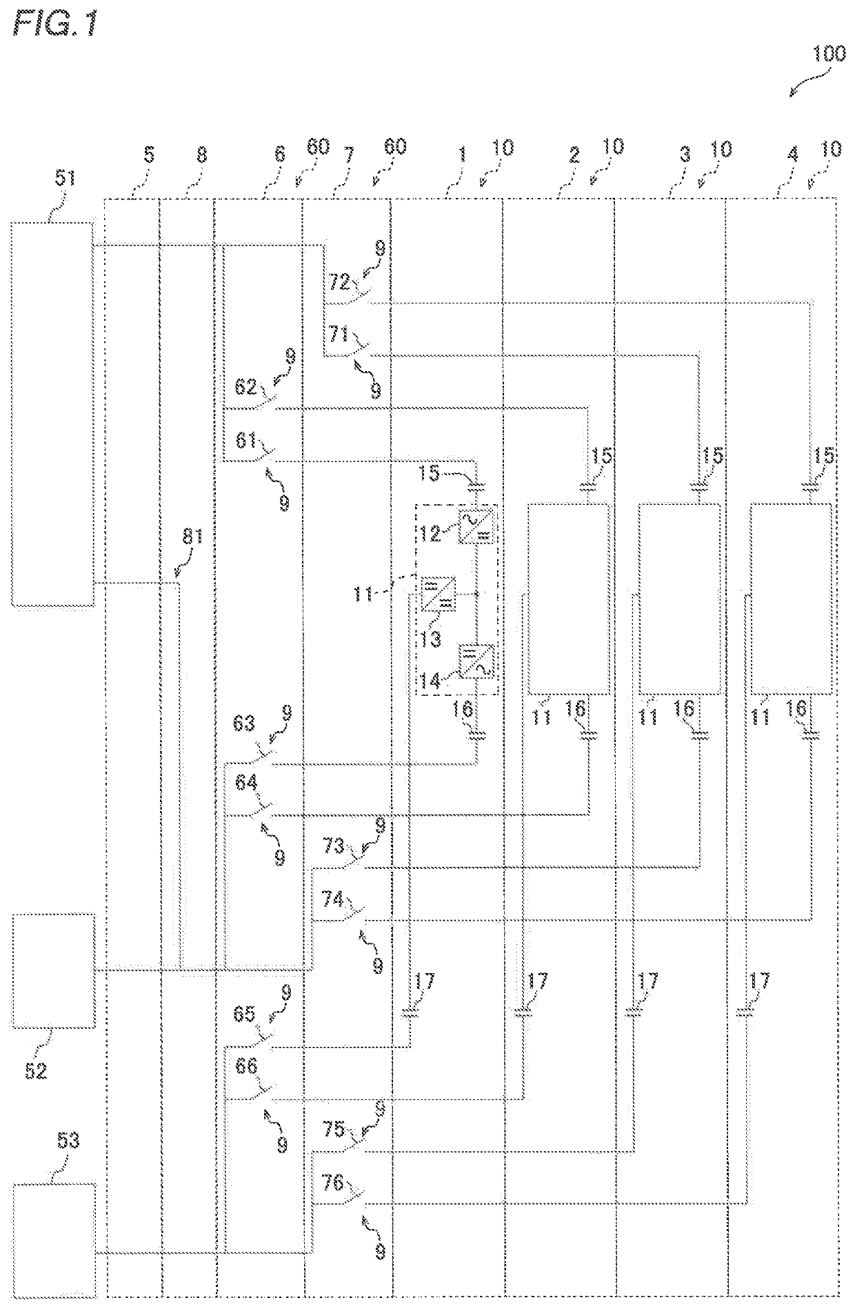
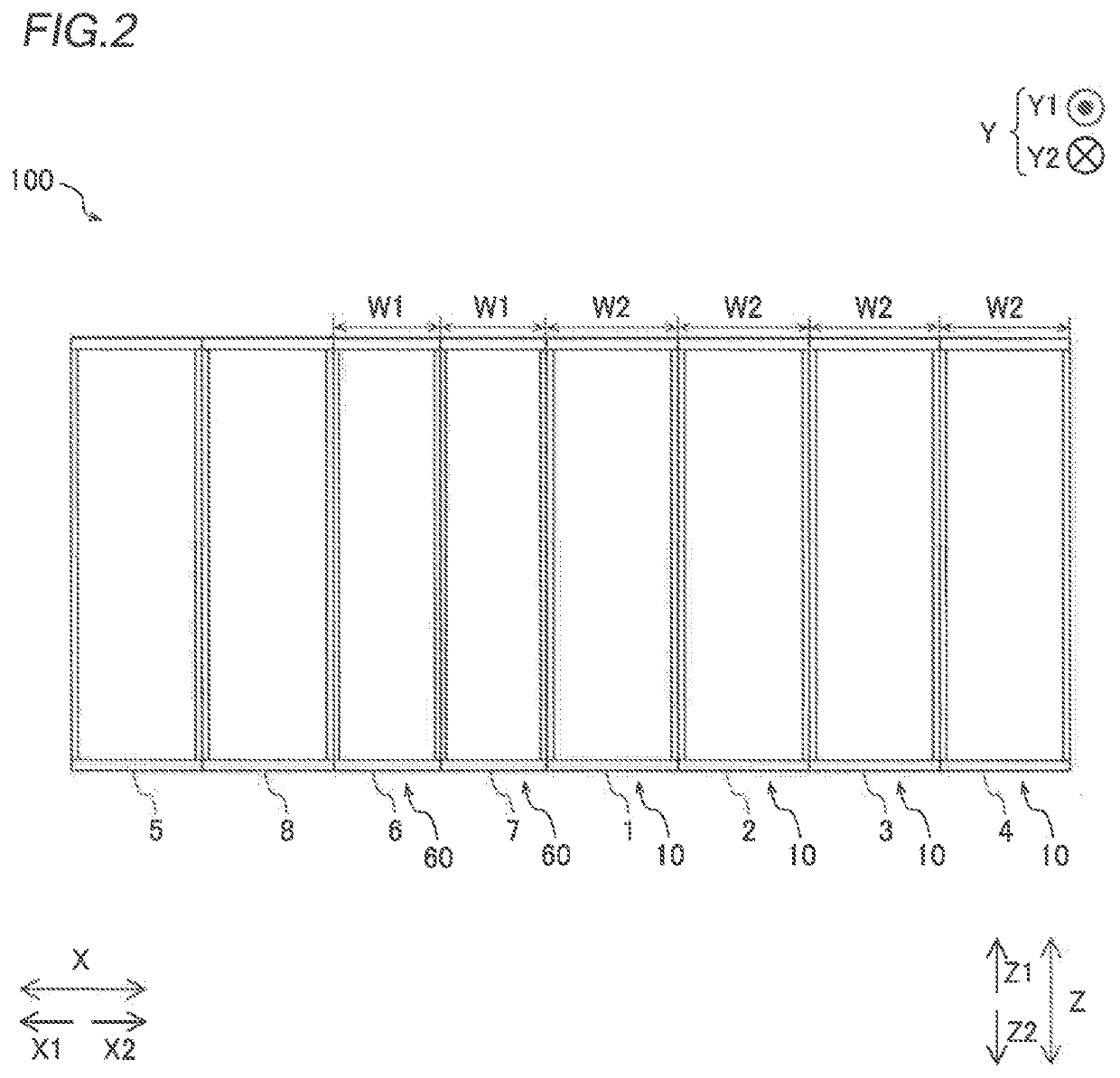
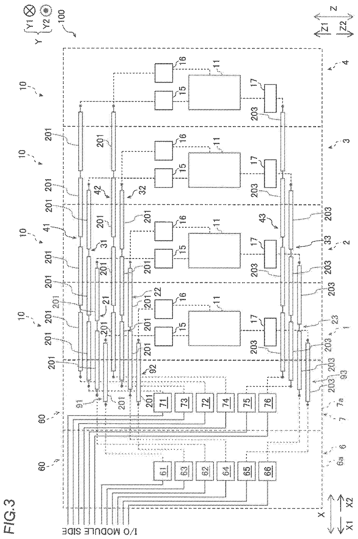
[0036]The circuit configuration and an arrangement of modules of an uninterruptible power supply 100 according to the present embodiment are now described with reference to FIGS. 1 to 3.

[0037]As shown in FIG. 1, the uninterruptible power supply 100 includes a plurality of uninterruptible power supply modules 10 (a first uninterruptible power supply module 1, a second uninterruptible power supply module 2, a third uninterruptible power supply module 3, and a fourth uninterruptible power supply module 4), an input / output module 5 (I / O module), and disconnection modules 60 (a first disconnection module 6 and a second disconnection module 7). Furthermore, the uninterruptible power supply 100 includes a control module 8. The uninterruptible power supply 100 is configured to receive three-phase (U-phase, V-phase, and W-phase) AC power a...


PUM


Abstract

An uninterruptible power supply includes disconnectors that perform a disconnection operation to electrically disconnect a plurality of uninterruptible power supply modules individually. Each of the disconnectors includes a connection conductor that electrically connects a first conductor to a second conductor, and a moving member mechanically moving the connection conductor in a direction in which the connection conductor approaches and contacts the first conductor and the second conductor, and a direction in which the connection conductor is spaced away from the first conductor and the second conductor.

Description

CROSS-REFERENCE TO RELATED APPLICATION[0001]The present application claims priority of Japanese Patent Application No. 2019-189504 filed Oct. 16, 2019, the disclosure of which is hereby incorporated by reference.BACKGROUND OF THE INVENTIONField of the Invention[0002]The present invention relates to an uninterruptible power supply and a disconnection module, and more particularly, it relates to an uninterruptible power supply and a disconnection module that perform a disconnection operation to electrically disconnect uninterruptible power supply modules.Description of the Background Art[0003]An uninterruptible power supply including a plurality of uninterruptible power supply modules is known in general, as disclosed in Japanese Patent Laid-Open No. 2011-072068, for example.[0004]Japanese Patent Laid-Open No. 2011-072068 discloses an uninterruptible power supply including a common AC input power supply and a plurality of uninterruptible power supply modules each including a power con...

Claims


Application Information

Patent Timeline
IPC IPC(8): H02J9/06G06F1/30H02M7/00
CPCH02J9/062H02M7/003G06F1/30
Inventor KOSHII, KEITAKIN, SEIITSUKUROZAKI, TOMO
Owner FUJI ELECTRIC CO LTD
Why Eureka
Try Eureka