MEMS universal inertia switch capable of identifying load orientation interval

An inertial switch and azimuth technology, which is applied in the direction of electric switches, contacts, electrical components, etc., can solve the problems of complex structure and inability to recover automatically, and achieve the effects of enhancing contact effect, preventing excessive displacement, and prolonging closing time

Active Publication Date: 2017-11-17
NANJING UNIV OF SCI & TECH
View PDF7 Cites 20 Cited by
  • Summary
  • Abstract
  • Description
  • Claims
  • Application Information

AI Technical Summary

Problems solved by technology

However, the switch is composed of 16 independent latching switches, the structure is complex, and it cannot be automatically

Method used


Image

  • MEMS universal inertia switch capable of identifying load orientation interval
  • MEMS universal inertia switch capable of identifying load orientation interval
  • MEMS universal inertia switch capable of identifying load orientation interval

Examples


Example Embodiment

[0041] Example 1

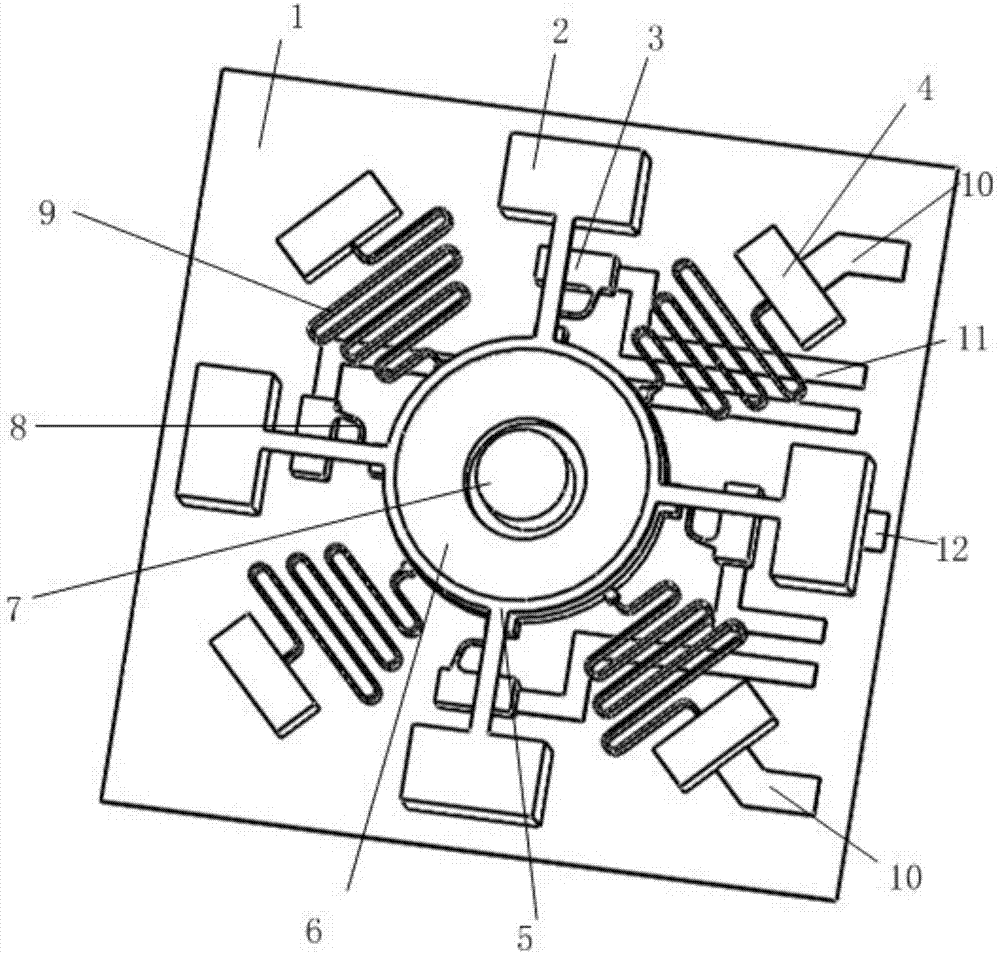
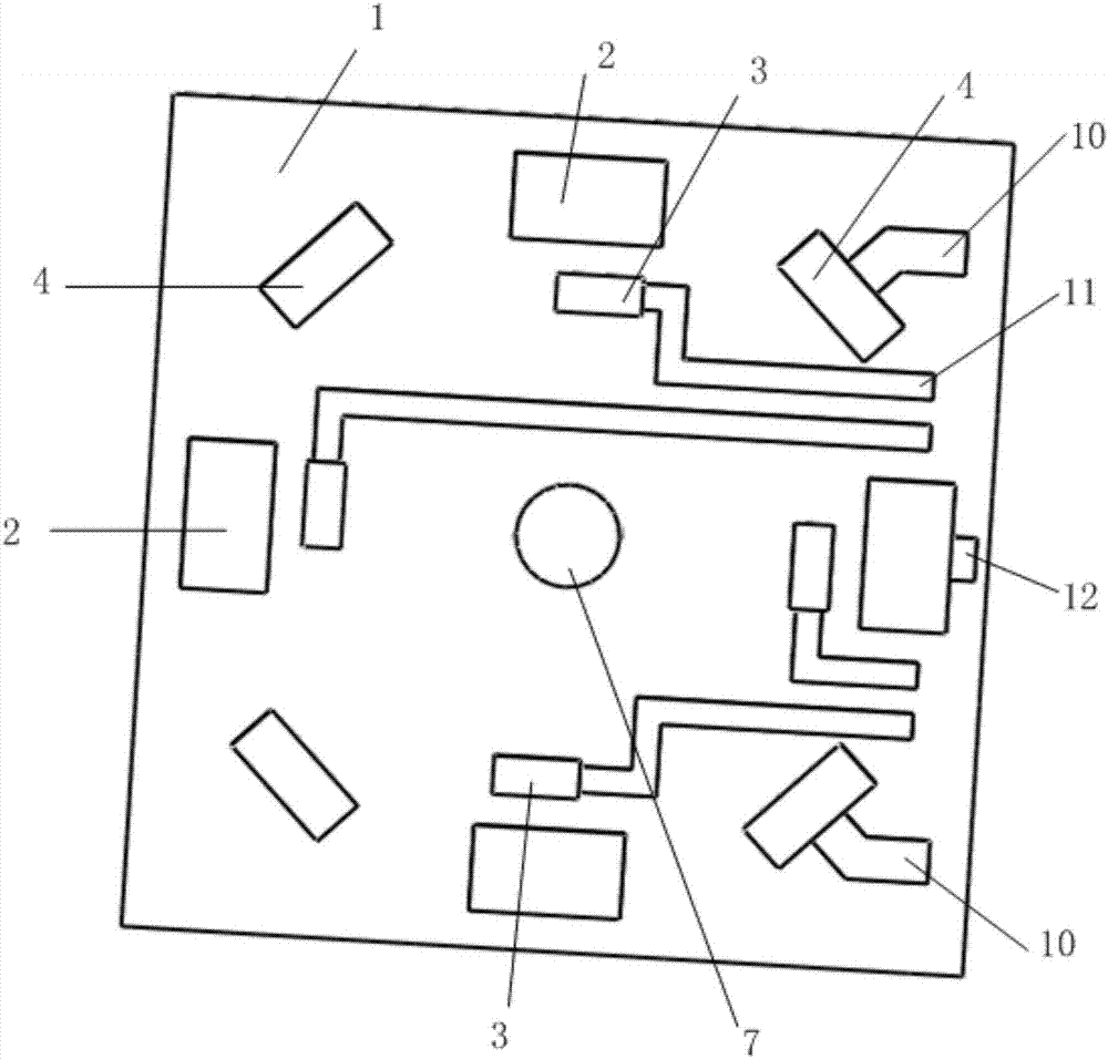
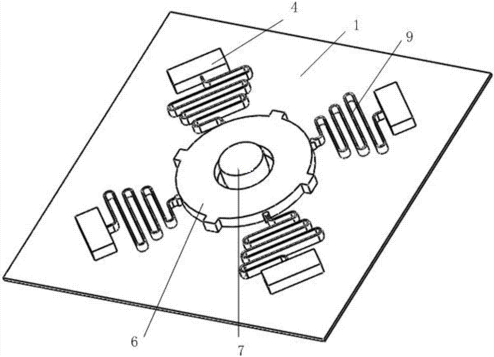
[0042] combine Figure 1 to Figure 5 , a MEMS universal inertial switch capable of identifying load azimuth intervals, including an insulating substrate 1, an axial electrode support seat 2, a radial electrode support seat 3, a spring support seat 4, an axial electrode 5, and an annular inertial mass electrode 6. Limit stop column 7, radial electrode 8, serpentine support spring 9, radial electrode connecting strip 11, axial electrode connecting strip 12 and two mass block electrode connecting strips 10, axial electrode support seat 2, The radial electrode support seat 3, the spring support seat 4, the limit stop post 7, the mass electrode connection strip 10, the radial electrode connection strip 11 and the axial electrode connection strip 12 are all arranged on the insulating substrate 1, and the axial The electrode support seat 2, the radial electrode support seat 3 and the spring support seat 4 are all used as anchor points; the limit stopper column 7 i...


PUM

PropertyMeasurementUnit
Line widthaaaaaaaaaa
Thicknessaaaaaaaaaa
Thicknessaaaaaaaaaa

Abstract

The present invention discloses an MEMS universal inertia switch capable of identifying a load orientation interval. The switch comprises an insulation substrate, an axial electrode supporting base, a radial electrode supporting base, a spring supporting base, an axial electrode, an annular inertia mass block electrode, a spacing stop post, a radial electrode, a snake-shaped support spring, a radial electrode connecting strip, a radial electrode connecting strip and at least one mass block electrode connecting strip. The MEMS universal inertia switch capable of identifying the load orientation interval has good response for the acceleration load at any one direction from the upper portion of the substrate to play a switch on/off effect, and can effectively identify the space orientation of the acceleration load which the switch has so as to solve the problem that a current MEMS universal inertia switch cannot identify the load space orientation, and the axial threshold of the closure of the switch is larger than a radial threshold thereof to realize axial deterring and radial sensitivity of the switch.

Description

technical field [0001] The invention belongs to a micro-electromechanical inertial device, in particular to a MEMS universal inertial switch capable of identifying load azimuth intervals. Background technique [0002] The MEMS inertial switch based on micro-electromechanical technology has the advantages of small size, light weight, low cost, and easy integration. It has urgent application needs and Wide application prospects, such as sensing recoil or centrifugal acceleration during ammunition launch, universal triggering of the fuze when the warhead hits the target, etc. In recent years, with the development of MEMS technology, from single-axis sensitivity to multi-axis sensitivity, from single threshold to multi-threshold development, researchers at home and abroad have designed a variety of MEMS inertial switch structures. For example, researchers from Shanghai Jiaotong University are extending the switch A lot of work has been done on the contact time and various struc...

Claims


Application Information

Patent Timeline
IPC IPC(8): H01H1/00H01H35/14
CPCH01H1/0036H01H35/146
Inventor 席占稳孔南聂伟荣曹云余平新
Owner NANJING UNIV OF SCI & TECH
Why Eureka
Try Eureka