Power conversion apparatus and controller thereof

a technology of power conversion apparatus and controller, which is applied in the direction of power conversion systems, dc-dc conversion, instruments, etc., can solve the problems of increasing the cost of the apparatus, and achieve the effects of low cost, high function, and extended off time of the switching elemen

Inactive Publication Date: 2013-02-26
SANKEN ELECTRIC CO LTD
View PDF11 Cites 6 Cited by
  • Summary
  • Abstract
  • Description
  • Claims
  • Application Information

AI Technical Summary

Benefits of technology

[0013]The power conversion apparatus according to the related art of FIG. 1 must provide the step-up transformer T1 with the second winding N2 to detect the ON timing of the switching element Q1. This increases the cost of the apparatus. If the second winding N2 short-circuits, the first winding N1 of the step-up transformer T1 will decrease inductance, to cause a malfunction of the apparatus.
[0014]The present invention provides a power conversion apparatus and a controller for the power conversion apparatus that are manufacturable at low cost, have high functions, and are capable of conducting an appropriate switching operation without auxiliary windings even when a difference between input and output voltages is small and a voltage detection error causes a great variation in an OFF time of a switching element.
[0019]According to the first and second aspects, the adjuster masks an ON time of a pulse signal from the pulse generator for a predetermined time, thereby providing the pulse signal with an adjusted ON time. The controller turns on / off the switching element according to a duty ratio corresponding to the adjusted ON time. The power conversion apparatus of the first and second aspects is manufacturable at low cost, has high functions, and is capable of conducting an appropriate switching operation without auxiliary windings even when a difference between input and output voltages is small and a voltage detection error causes a great variation in an OFF time of the switching element.
[0020]According to the third and fourth aspects, the adjuster adjusts a duty ratio of a pulse signal from the pulse generator so as to extend an OFF time of the switching element. The controller turns on / off the switching element according to the adjusted duty ratio. The power conversion apparatus of the third and fourth aspects is manufacturable at low cost, has high functions, and is capable of conducting an appropriate switching operation without auxiliary windings even when a difference between input and output voltages is small and a voltage detection error causes a great variation in an OFF time of the switching element.

Problems solved by technology

This increases the cost of the apparatus.

Method used


Image

  • Power conversion apparatus and controller thereof
  • Power conversion apparatus and controller thereof
  • Power conversion apparatus and controller thereof

Examples


embodiment 1

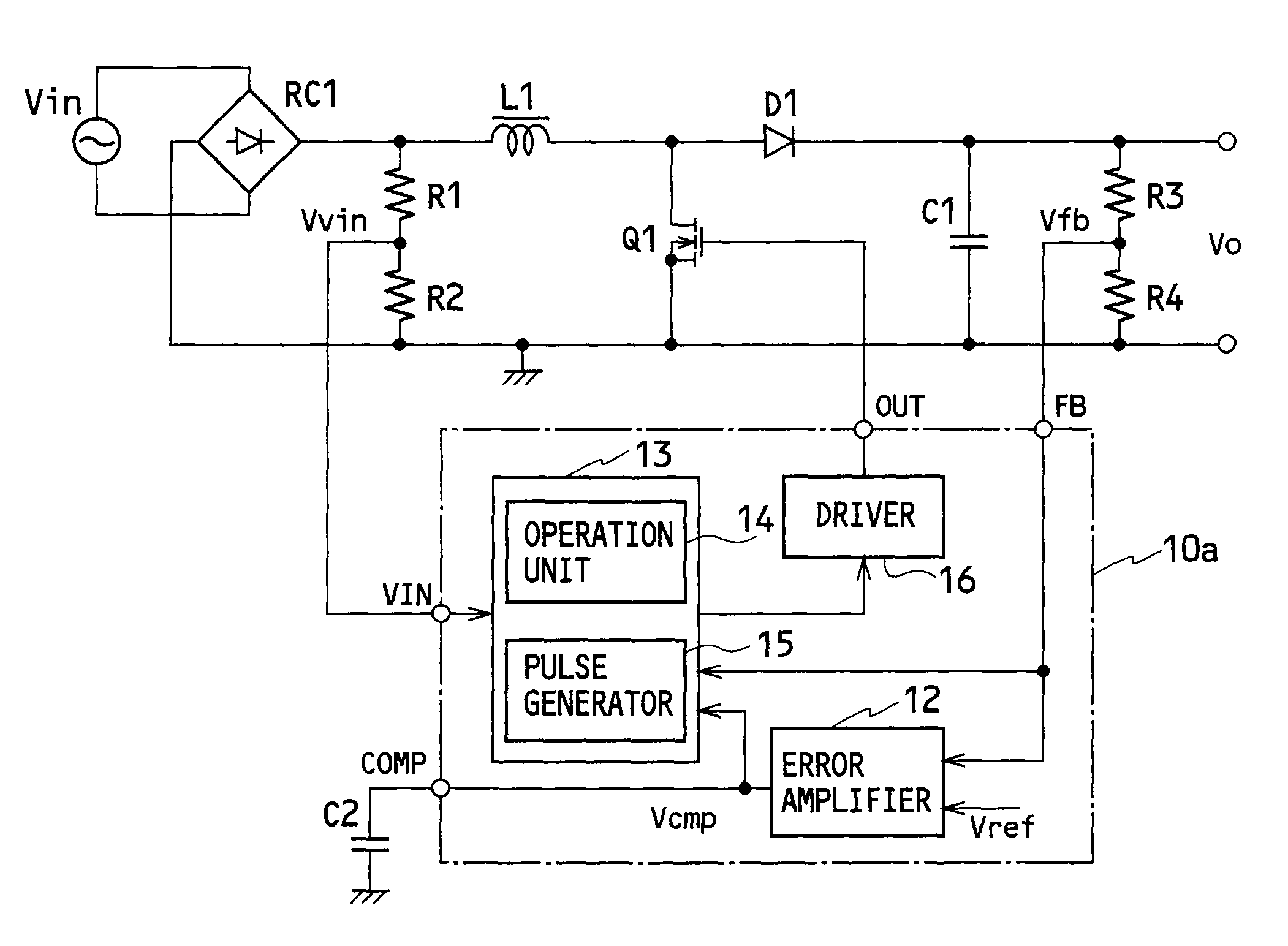
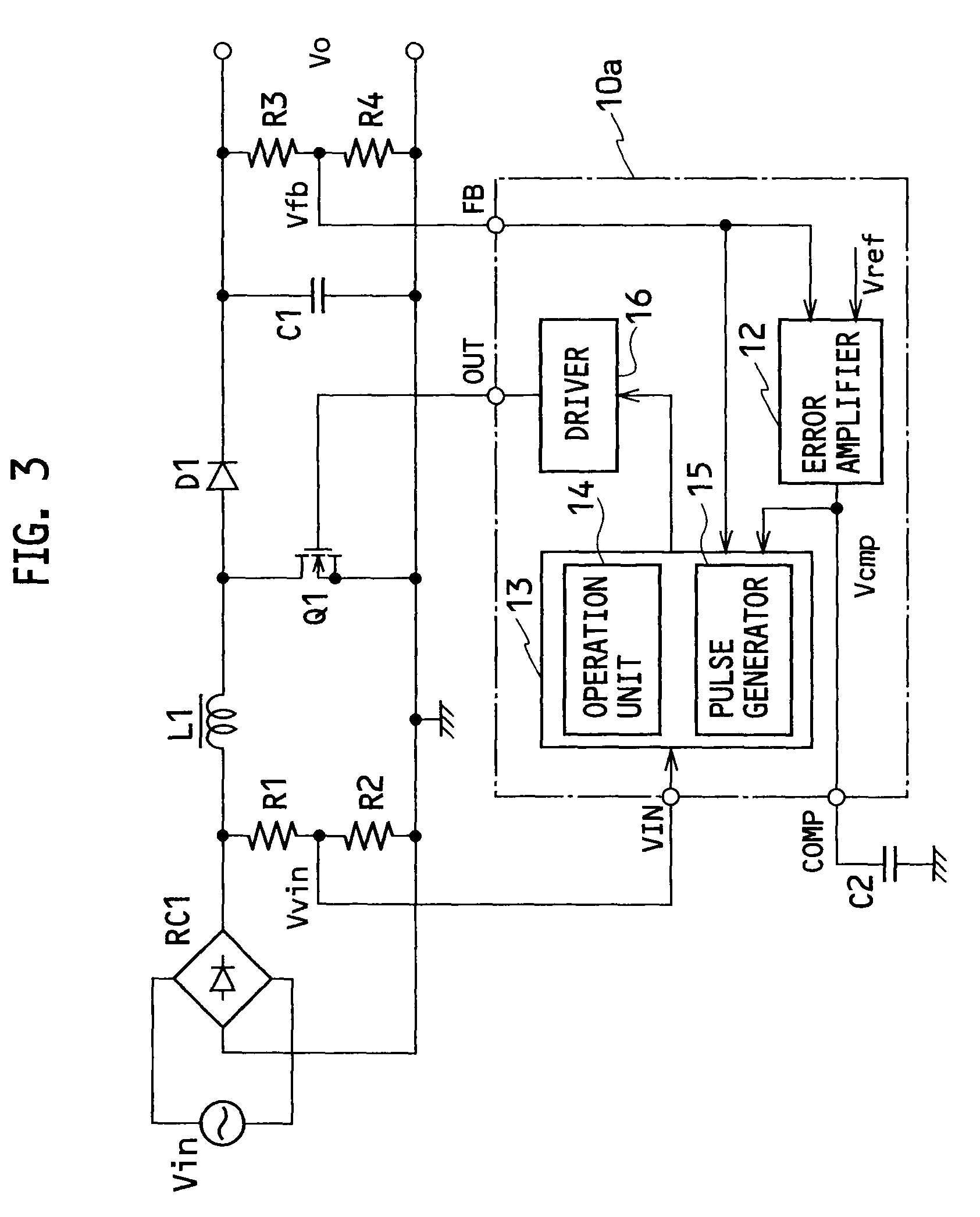
[0038]FIG. 3 is a circuit diagram illustrating a power conversion apparatus according to Embodiment 1 of the present invention. In this power conversion apparatus, a rectifier RC1 rectifies an AC voltage from an AC power source Vin into a DC voltage. Both output ends of the rectifier RC1 are connected to a series circuit including a step-up reactor L1 and a switching element Q1 made of a MOSFET and to a series circuit including resistors R1 and R2.

[0039]Both ends of the switching element Q1 are connected to a rectifying-smoothing circuit including a rectifier D1 and a smoothing capacitor C1. Both ends of the smoothing capacitor C1 are connected to a series circuit including resistors R3 and R4.

[0040]The resistors R1 and R2 constitute an input voltage detector that divides an output voltage from the rectifier RC1 at a connection point of the resistors R1 and R2 and provides an input voltage signal Vvin. The resistors R3 and R4 constitute an output voltage detector that divides a volt...

embodiment 2

[0066]A power conversion apparatus according to Embodiment 2 of the present invention will be explained. The power conversion apparatus of Embodiment 1 will deteriorate power factor and efficiency or excessively decrease a switching frequency lower than an audible frequency, if the input voltage signal Vvin and output voltage signal Vfb are incorrectly measured.

[0067]If the output voltage Vo is 385 V and the input voltage Vin is 100 V, the OFF time Toff of the switching element Q1 will be 0.35 times the ON time Ton of the switching element Q1. At this time, if the input voltage Vin and output voltage Vo are detected with a voltage detection error of ±1%, the OFF time Toff will vary in the range of 0.34 to 0.36 times the ON time Ton. This variation of the OFF time is ignorable.

[0068]If the output voltage Vo is 385 V and the input voltage Vin is 375 V, the OFF time Toff will be 37.5 times the ON time Ton. At this time, if the input voltage Vin and output voltage Vo are detected with a...

embodiment 3

[0082]FIG. 12 is a circuit diagram illustrating a power conversion apparatus according to Embodiment 3 of the present invention. Embodiment 3 differs from Embodiment 2 in that Embodiment 3 employs an interleave converter configuration including first and second converters connected in parallel. The first converter has a step-up reactor L1, a switching element Q1, and a diode D1. The second converter has a step-up reactor L2, a switching element Q2, and a diode D2.

[0083]An input current sensing resistor R5 as a current sensor is connected to the interleave converter and a negative terminal of a rectifier RC1, to detect and provide an input current signal Vis, which is supplied to an oscillator 13a in a controller 10c. The oscillator 13a provides first and second drive signals according to which a driver 16a turns on / off the switching elements Q1 and Q2.

[0084]FIG. 13 is a circuit diagram illustrating a pulse generator 15a and the driver 16a in the power conversion apparatus according ...


PUM


Abstract

A power conversion apparatus includes a converter having an input power source Vin, a reactor L1, a switching element Q1, and a rectifying element D1, a smoothing capacitor C1 connected to an output terminal of the converter, and a controller 10b to turn on / off the switching element and thereby control power to be outputted from the converter. The controller has a pulse generator 15 to generate a pulse signal according to an input voltage to the converter and an output voltage from the converter, the pulse signal being used to turn on / off the switching element. The controller also has an adjuster 18 to mask an ON time of the pulse signal for a predetermined time and thereby provide the pulse signal with an adjusted ON time, the adjusted ON time determining a duty ratio at which the switching element is turned on / off.

Description

BACKGROUND OF THE INVENTION[0001]1. Field of the Invention[0002]The present invention relates to a power conversion apparatus and a controller for the power conversion apparatus.[0003]2. Description of the Related Art[0004]FIG. 1 is a circuit diagram illustrating a power conversion apparatus according to a related art. This power conversion apparatus is a current-critical power factor correction circuit.[0005]In the power conversion apparatus of FIG. 1, a rectifier RC1 rectifies an AC voltage from an AC power source Vin into a DC voltage. Both output ends of the rectifier RC1 are connected to a series circuit that includes a first winding N1 of a step-up transformer T1, a switching element Q1 made of a MOSFET, and a current sensing resistor R5. The output ends of the rectifier RC1 are also connected to a series circuit of resistors R1 and R2.[0006]Both ends of a series circuit of the switching element Q1 and current sensing resistor R5 are connected to a rectifying-smoothing circuit...

Claims


Application Information

Patent Timeline
Patent Type & Authority Patents(United States)
IPC IPC(8): G05F1/00
CPCH02M3/156
Inventor OSAKA, SHOHEI
Owner SANKEN ELECTRIC CO LTD
Why Eureka
Try Eureka