Switching power source apparatus

Active Publication Date: 2012-12-06
SANKEN ELECTRIC CO LTD
View PDF9 Cites 32 Cited by
  • Summary
  • Abstract
  • Description
  • Claims
  • Application Information

AI Technical Summary

Benefits of technology

[0010]The switching power source apparatus according to the related art of FIG. 1 must have six drivers to drive

Problems solved by technology

The switching power source apparatus according to the related art of FIG. 1 must have six drivers to drive gates of the six switching elements Q1 to Q6, to c

Method used


Image

  • Switching power source apparatus
  • Switching power source apparatus
  • Switching power source apparatus

Examples


embodiment 1

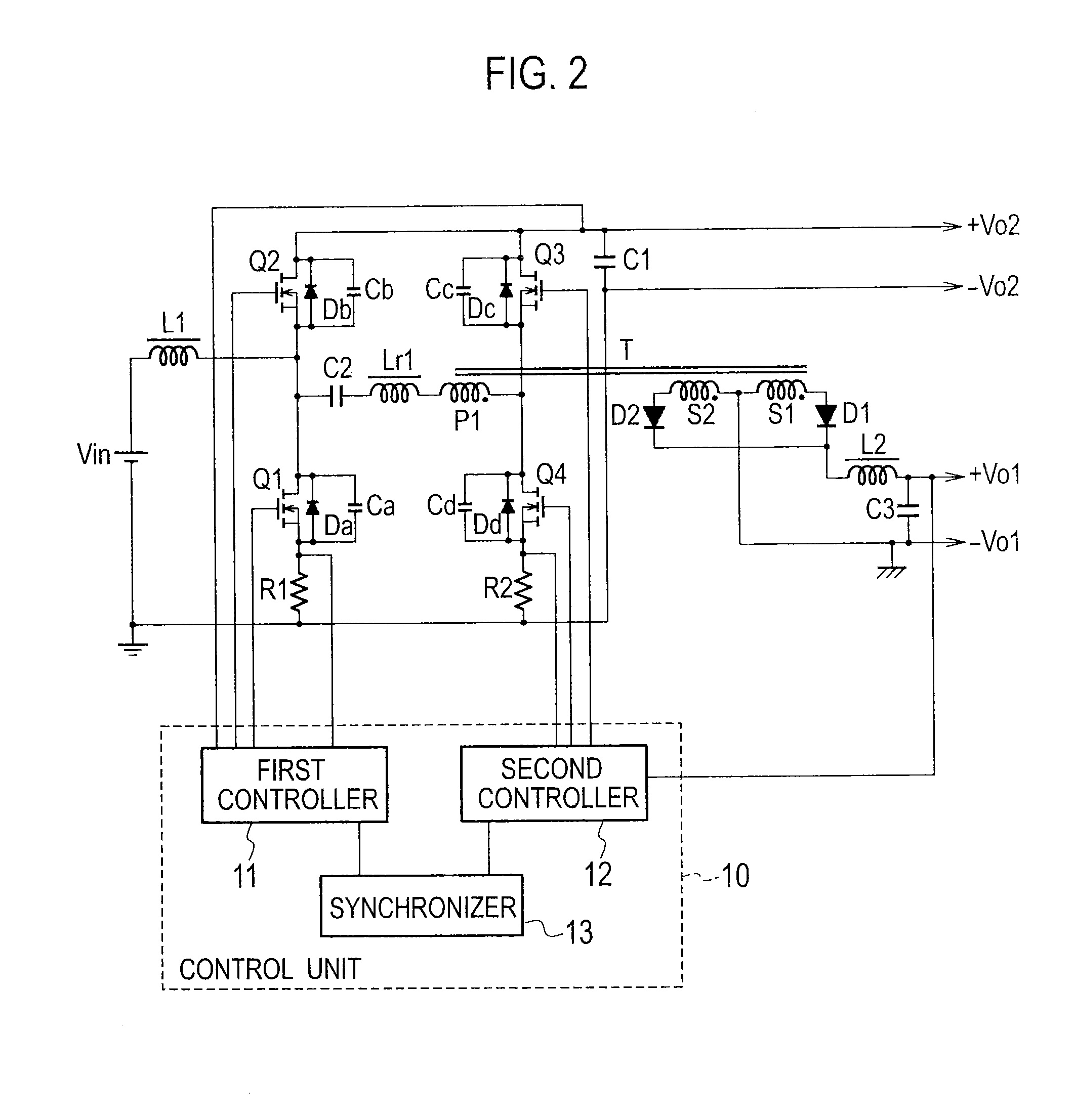
[0027]FIG. 2 is a schematic view illustrating a switching power source apparatus according to Embodiment 1 of the present invention. This switching power source apparatus includes a first converter as a step-up converter and a second converter as a DC-DC converter. The first and second converters are linked to each other through a transformer T, a capacitor C2, and a reactor Lr1 with the use of gate pulses.

[0028]The first converter is a synchronous rectification step-up circuit and includes a reactor L1, a switching element Q1 serving as a main control switch, a switching element Q2 serving as an auxiliary control switch (synchronous rectification switch), a capacitor C1, and a first controller 11. The switching elements Q1 and Q2 are a first arm.

[0029]The second converter is a half-bridge forward converter and includes a switching element Q3 serving as a main control switch, a switching element Q4 serving as an auxiliary control switch (synchronous rectification switch), capacitors...

embodiment 2

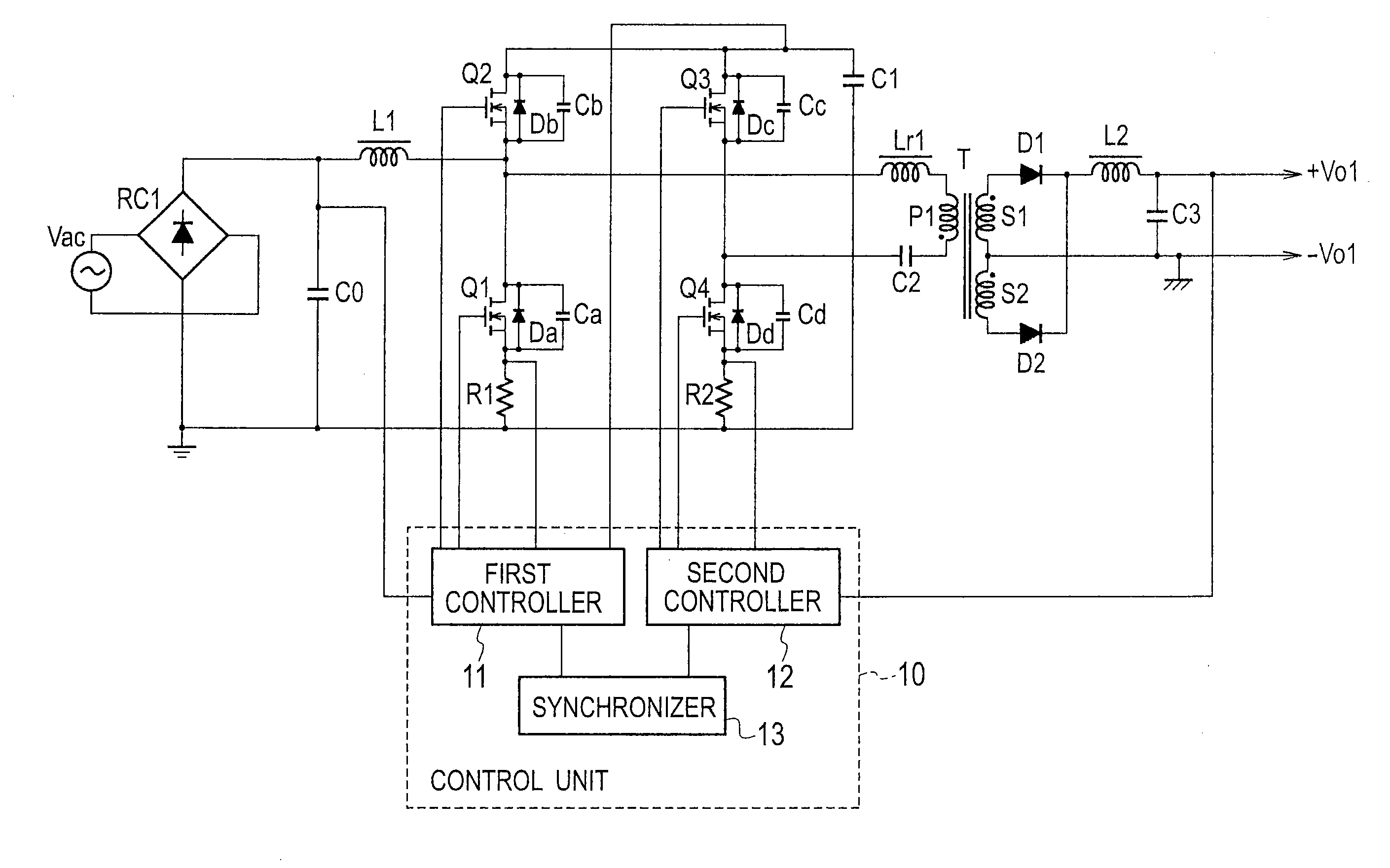
[0088]FIG. 8 is a schematic view illustrating a switching power source apparatus according to Embodiment 2 of the present invention. Instead of the DC power source Vin of Embodiment 1 illustrated in FIG. 2, Embodiment 2 of FIG. 8 employs a PFC (power factor correction) circuit involving an AC power source Vac, a rectifier RC1, and a capacitor C0.

[0089]The AC power source Vac supplies an AC voltage to the rectifier RC1, which rectifies the AC voltage.

[0090]Both output ends of the rectifier RC1 are connected to the capacitor C0. A first controller 11 receives a voltage of the capacitor C0, multiplies the pulsating output voltage of the capacitor C0 by an output error voltage of a capacitor C1, and according to a result of the multiplication and a voltage from a current detecting resistor R1, equalizes an input AC current waveform with an input AC voltage waveform, thereby correcting a power factor.

[0091]With this configuration, the switching power source apparatus according to Embodim...

embodiment 3

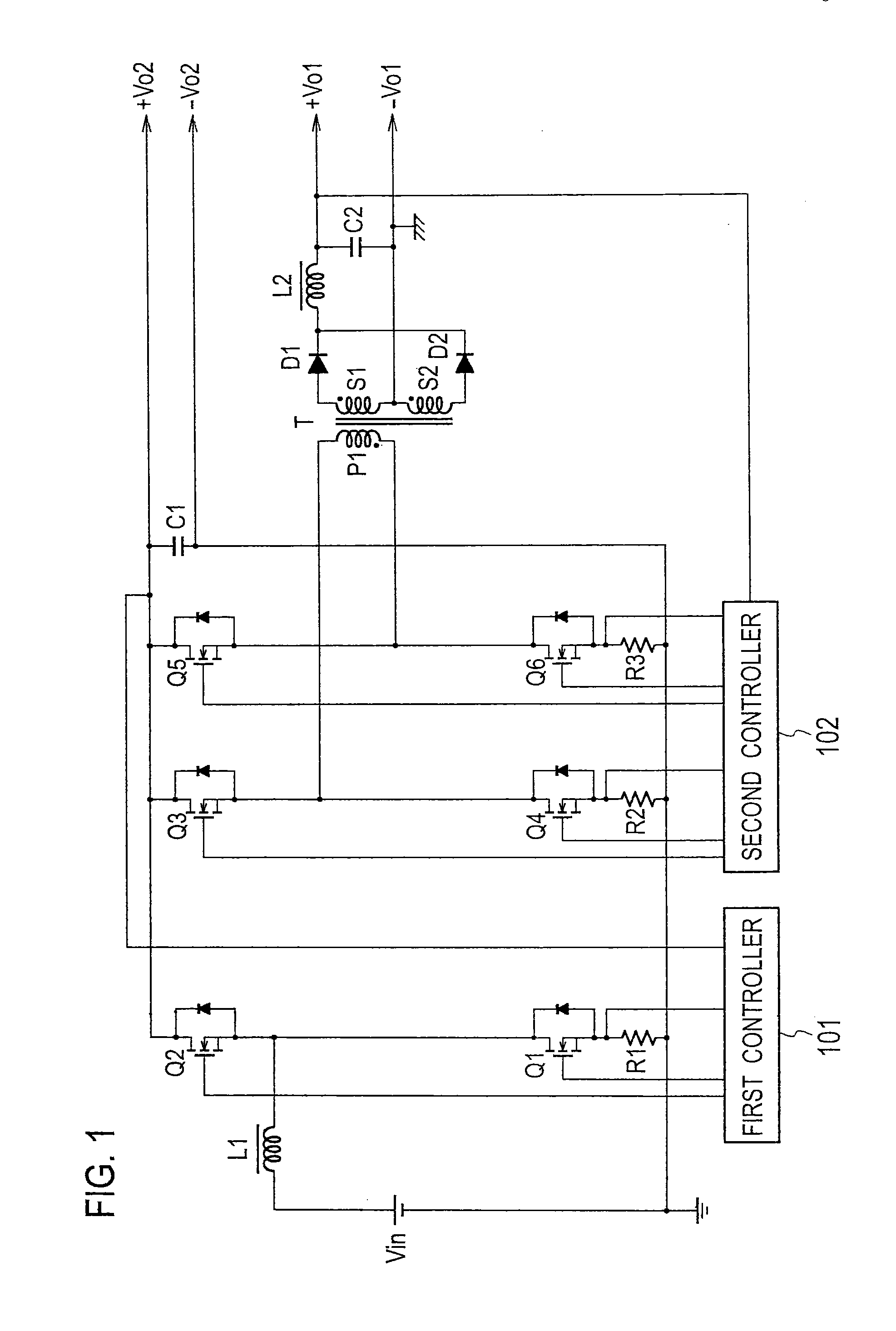
[0093]FIG. 9 is a schematic view illustrating a switching power source apparatus according to Embodiment 3 of the present invention. This switching power source apparatus includes a non-insulated step-down circuit and an insulated circuit.

[0094]Both ends of a DC power source Vin are connected through a current detecting resistor R1 to a series circuit including a switching element Q1 serving as a main control switch and a switching element Q2 serving as an auxiliary control switch (synchronous rectification switch) and through a current detecting resistor R2 to a series circuit including a switching element Q3 serving as a main control switch and a switching element Q4 serving as an auxiliary control switch (synchronous rectification switch). Connected between a connection point of the switching elements Q1 and Q2 and a connection point of the switching elements Q3 and Q4 is a series circuit including a capacitor C2, a primary winding P1 of a transformer T, and a reactor Lr1. The se...


PUM


Abstract

A switching power source apparatus includes a first arm including first and second switching elements, a second arm including third and fourth switching elements, a series circuit connected between a connection point of the first and second switching elements and a connection point of the third and fourth switching elements and including a capacitor and a primary winding, a rectifying-smoothing circuit that rectifies and smoothes a voltage of a secondary winding and provides an output voltage, a reactor connected to a connection point of the first and second switching elements and a DC input end, and a controller that turns on/off the first and second switching elements alternately and the third and fourth switching elements alternately and synchronizes the first and third switching elements with each other and the second and fourth switching elements with each other.

Description

BACKGROUND OF THE INVENTION[0001]1. Field of the Invention[0002]The present invention relates to a switching power source apparatus that is highly efficient and involves a low switching loss.[0003]2. Description of Related Art[0004]FIG. 1 illustrates a switching power source apparatus according to a related art. This switching power source apparatus includes a step-up converter and an isolated full-bridge circuit. The step-up converter includes a DC power source Vin, a reactor L1, switching elements Q1 and Q2 of MOSFETs, a current detecting resistor R1, a capacitor C1, and a first controller 101.[0005]According to a voltage from the capacitor C1 and a voltage from the current detecting resistor R1, the first controller 101 turns on / off the switching elements Q1 and Q2 alternately so as to provide, from both ends of the capacitor C1, a constant output voltage Vo2 that is higher than an input voltage from the DC power source Vin.[0006]The isolated full-bridge circuit includes switchin...

Claims


Application Information

Patent Timeline
IPC IPC(8): H02M3/335
CPCH02M3/3376H02M1/08
Inventor CHIBA, AKITERU
Owner SANKEN ELECTRIC CO LTD
Why Eureka
Try Eureka