Inverter bridge switching power source utlizing a capacitor with transformer for multiple outputs
a technology of switching power source and transformer, applied in the direction of electric variable regulation, process and machine control, instruments, etc., can solve the problems complicating the three-phase inverter module, and complicating the apparatus. , to achieve the effect of increasing the cost of the apparatus and complicating the apparatus
- Summary
- Abstract
- Description
- Claims
- Application Information
AI Technical Summary
Benefits of technology
Problems solved by technology
Method used
Image
Examples
embodiment 1
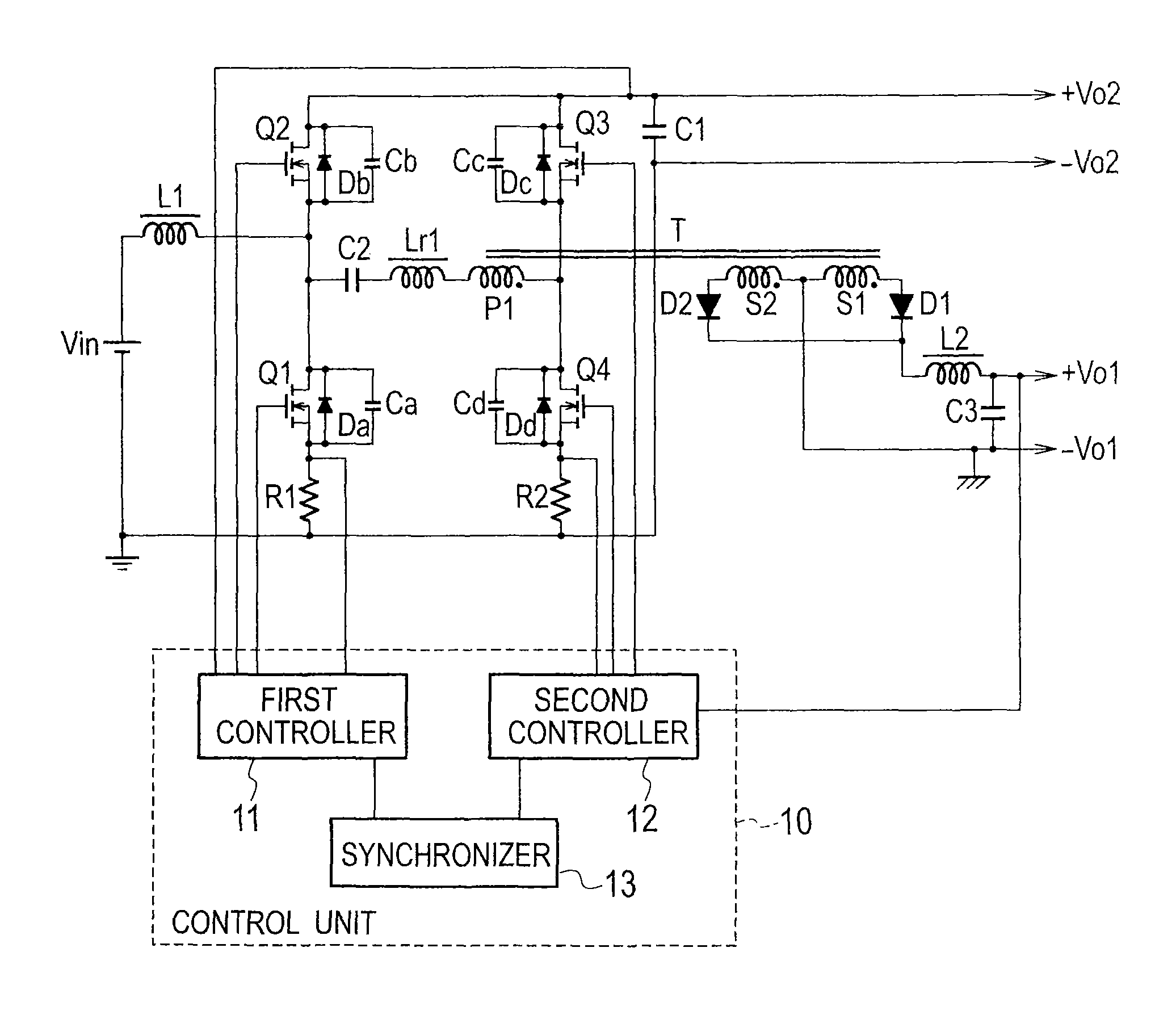
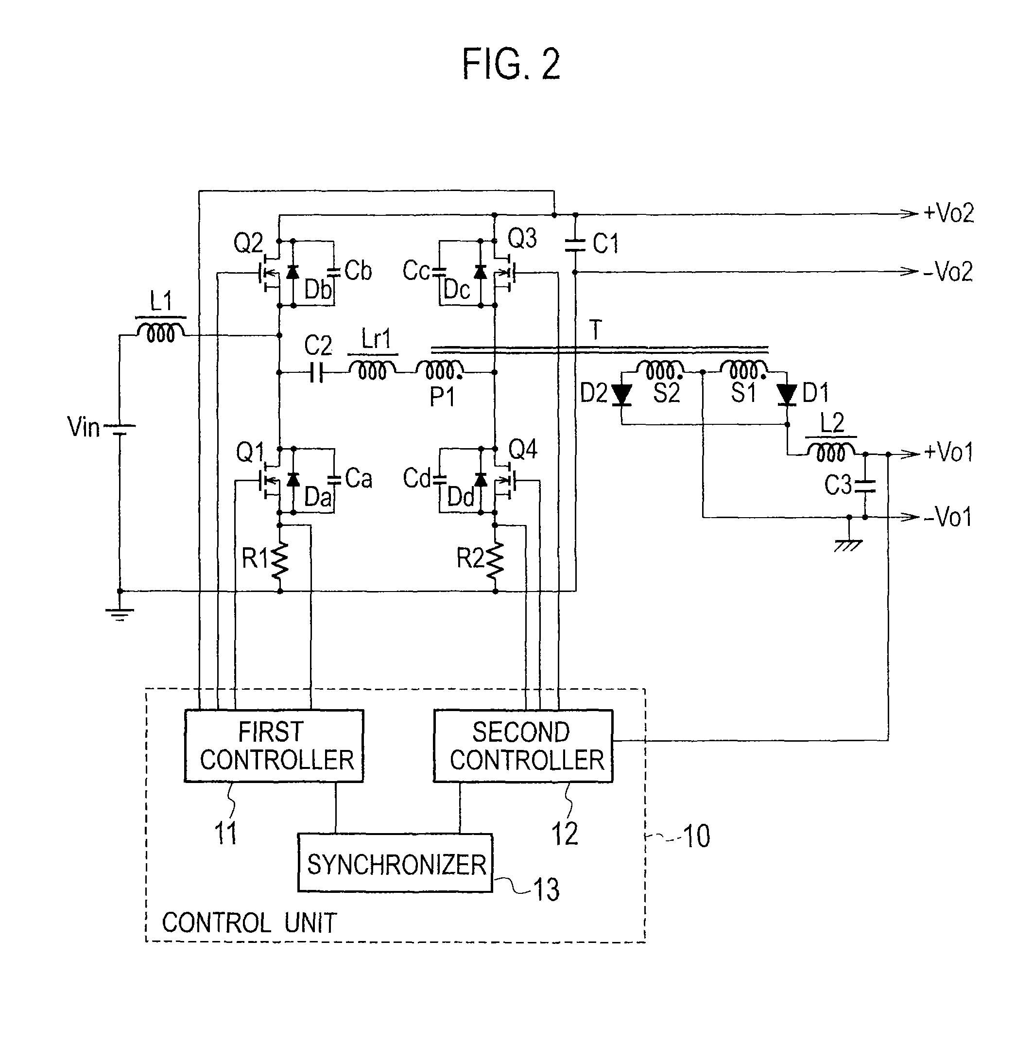
[0027]FIG. 2 is a schematic view illustrating a switching power source apparatus according to Embodiment 1 of the present invention. This switching power source apparatus includes a first converter as a step-up converter and a second converter as a DC-DC converter. The first and second converters are linked to each other through a transformer T, a capacitor C2, and a reactor Lr1 with the use of gate pulses.
[0028]The first converter is a synchronous rectification step-up circuit and includes a reactor L1, a switching element Q1 serving as a main control switch, a switching element Q2 serving as an auxiliary control switch (synchronous rectification switch), a capacitor C1, and a first controller 11. The switching elements Q1 and Q2 are a first arm.
[0029]The second converter is a half-bridge forward converter and includes a switching element Q3 serving as a main control switch, a switching element Q4 serving as an auxiliary control switch (synchronous rectification switch), capacitors...
embodiment 2
[0087]FIG. 8 is a schematic view illustrating a switching power source apparatus according to Embodiment 2 of the present invention. Instead of the DC power source Vin of Embodiment 1 illustrated in FIG. 2, Embodiment 2 of FIG. 8 employs a PFC (power factor correction) circuit involving an AC power source Vac, a rectifier RC1, and a capacitor C0.
[0088]The AC power source Vac supplies an AC voltage to the rectifier RC1, which rectifies the AC voltage.
[0089]Both output ends of the rectifier RC1 are connected to the capacitor C0. A first controller 11 receives a voltage of the capacitor C0, multiplies the pulsating output voltage of the capacitor C0 by an output error voltage of a capacitor C1, and according to a result of the multiplication and a voltage from a current detecting resistor R1, equalizes an input AC current waveform with an input AC voltage waveform, thereby correcting a power factor.
[0090]With this configuration, the switching power source apparatus according to Embodim...
embodiment 3
[0092]FIG. 9 is a schematic view illustrating a switching power source apparatus according to Embodiment 3 of the present invention. This switching power source apparatus includes a non-insulated step-down circuit and an insulated circuit.
[0093]Both ends of a DC power source Vin are connected through a current detecting resistor R1 to a series circuit including a switching element Q1 serving as a main control switch and a switching element Q2 serving as an auxiliary control switch (synchronous rectification switch) and through a current detecting resistor R2 to a series circuit including a switching element Q3 serving as a main control switch and a switching element Q4 serving as an auxiliary control switch (synchronous rectification switch). Connected between a connection point of the switching elements Q1 and Q2 and a connection point of the switching elements Q3 and Q4 is a series circuit including a capacitor C2, a primary winding P1 of a transformer T, and a reactor Lr1. The se...
PUM
 Abstract
Description
Claims
Application Information
 - R&D
- Intellectual Property
- Life Sciences
- Materials
- Tech Scout
- Unparalleled Data Quality
- Higher Quality Content
- 60% Fewer Hallucinations
Browse by: Latest US Patents, China's latest patents, Technical Efficacy Thesaurus, Application Domain, Technology Topic, Popular Technical Reports.
© 2025 PatSnap. All rights reserved.Legal|Privacy policy|Modern Slavery Act Transparency Statement|Sitemap|About US| Contact US: help@patsnap.com


