
Multi-stage gravity-type sludge drying apparatus and method for drying sludge using same

Active Publication Date: 2021-11-02
NANCHANG HANGKONG UNIVERSITY
View PDF16 Cites 0 Cited by
  • Summary
  • Abstract
  • Description
  • Claims
  • Application Information

AI Technical Summary

Benefits of technology

The technical effect of this patent is to provide a multi-stage gravity-type sludge drying apparatus and a method for drying sludge that overcomes the defects in the prior art such as high energy consumption, complicated apparatus, difficult maintenance, adhesion and slow drying rate.

Problems solved by technology

The drying process will result in large energy consumption, and the characteristics of sludge, such as complex composition and high moisture content, make the drying more complicated.
Moreover, condensation will occur in the early period of the drying, which may increase the moisture content, reducing the drying efficiency of the sludge.
There are various sticky substances in the sludge such as organic matters, which may cause a blockage during the transportation and the occurrence of wall sticking.
During the drying process, the occurrence of wall sticking not only increases the thermal resistance and reduces the drying efficiency, but also causes security risks to the drying apparatus.
Moreover, it has been found by Feng Liu (Study of town sludge stickiness in drying process[D], Tianjin University, 2018) that the drying completely occurs on the surface of the sludge at the early stage, and with the evaporation of water, gaps gradually appear inside the sludge, which indicates the occurrence of shrinkage.
With the progress of shrinkage, the surface tension and the viscosity of the sludge decrease, and cracks appear on the surface.
(Progress and Techniques for Thermal Sludge Drying at Home and Abroad[J], China Water & Wastewater, 2007, 23 (8): 5-8) has demonstrated that in the indirect thermal-conduction drying, the drying medium can be recycled, however, in the case of high moisture content, the sludge is prone to wall sticking, resulting in high heat transfer resistance, large energy consumption and low drying efficiency. weiyun Wang (Study on indirect thin-layer drying and dehydration drying coupled with thermal pressure of sludge[D], Dalian University of Technology, 2012) has found that during the indirect drying, the closer the sludge to the heat transfer surface is, the faster the moisture content will be reduced.
However, this method involves the considerable production of tail gas.
Moreover, during the steam or water separation, the separated water brings out a large amount of energy, and there is still a considerable amount of gas mixed in the steam, causing damage to the compressor and reducing the drying effect.
Although the latent heat from the superheated steam drying is recovered, the heat exchange efficiency of the heat exchanger is not satisfactory.
In addition, the re-generation of steam from hot water involves large energy consumption, so this method actually only achieves energy conservation to a certain extent.

Method used


Image

  • Multi-stage gravity-type sludge drying apparatus and method for drying sludge using same
  • Multi-stage gravity-type sludge drying apparatus and method for drying sludge using same
  • Multi-stage gravity-type sludge drying apparatus and method for drying sludge using same

Examples


Embodiment Construction

[0062]The technical solutions in the embodiments of the invention will be clearly and completely described below with reference to the drawings. Obviously, the described embodiments are only part of the embodiments of the invention, and are not intended to limit the invention. Other embodiments obtained by those skilled in the art without sparing any creative efforts shall fall within the scope of the invention.

[0063]An object of the invention is to provide a multi-stage gravity-type sludge drying apparatus and a drying method using the same to solve the problems in the prior art such as high energy consumption, complicated apparatus, difficult maintenance, wall sticking and slow drying rate.

[0064]In order to make the objects, features and advantages of the invention more obvious and understood, the invention will be further described with reference to the drawings and embodiments.

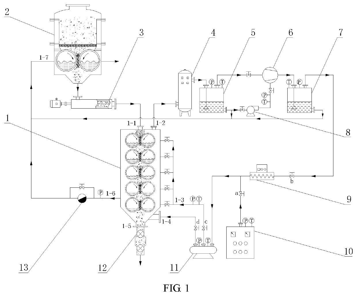
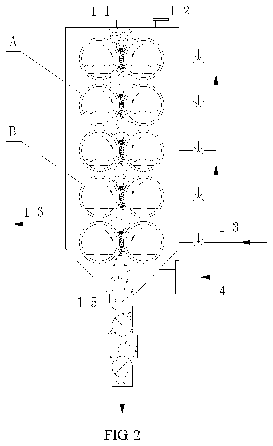
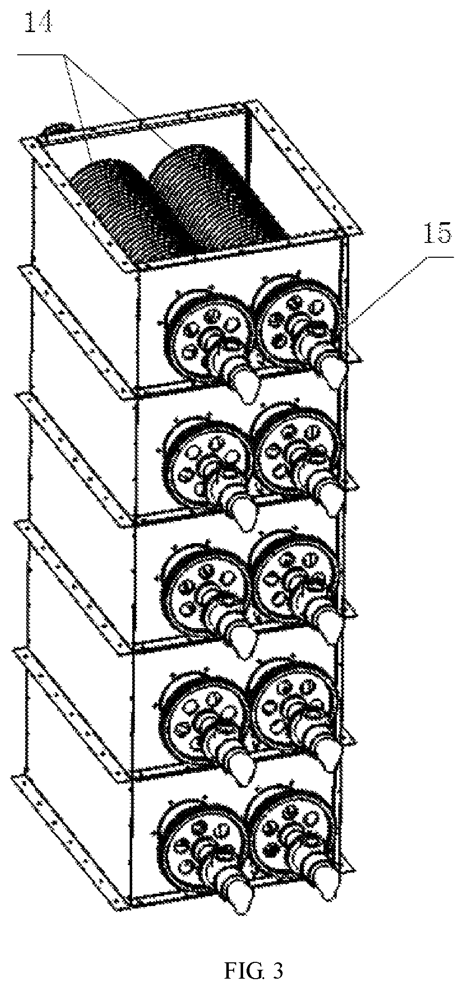
[0065]The sludge drying apparatus of the present invention is shown in the figures. FIG. 1 is a schemat...


PUM


Abstract

Disclosed are a multi-stage gravity-type sludge drying apparatus and a sludge drying method using the same. The drying apparatus includes: a dryer, a preheater, a steam generator, a filter, a steam or water separation buffer tank, a steam compressor, a cooling water pump, a sealed discharge device, pipes and valves. The dryer includes several indirect dryer modules. The transportation of sludge in the dryer is achieved by gravity. The inner cavity of respective indirect dryers is filled with high-temperature steam to dry the sludge by indirect heating. The condensate water in the cavity is recycled and fed into the preheater to perform preheating and impurity removal on the wet sludge. The secondary steam generated in the dryer is filtered, compressed and overheated to become a new heat source for indirect heating in the cavity and convection drying at a bottom of the dryer.

Description

CROSS-REFERENCE TO RELATED APPLICATIONS[0001]This application claims the benefit of priority from Chinese Patent Application No. 201910449886.0, filed on May 28, 2019. The content of the aforementioned application, including any intervening amendments thereto, is incorporated herein by reference in its entirety.TECHNICAL FIELD[0002]The present application relates to sludge drying, and more particularly to a multi-stage gravity-type sludge drying apparatus and a method for drying sludge using the same.BACKGROUND OF THE INVENTION[0003]Reducing the moisture content in sludge is an effective way for sludge reduction, and the sludge can be rapidly dried through thermal evaporation. Several aspects should be taken into consideration during the sludge drying process, such as the selection of drying apparatus, energy consumption, drying rate and the treatment of secondary product. The drying process will result in large energy consumption, and the characteristics of sludge, such as complex ...

Claims


Application Information

Patent Timeline
IPC IPC(8): F26B3/32C02F11/13C02F11/121F26B23/00
CPCC02F11/13C02F11/121F26B23/004C02F2303/10F26B2200/18Y02W10/30Y02W10/37
Inventor ZHANG, XUKUNCHEN, MENGWU, XIAOWANGYANG, ZHU ANGAN, MAOYUNZOU, XUEPINGXING, PUZHU, BAOLI
Owner NANCHANG HANGKONG UNIVERSITY
Learn More