Received data processing apparatus of photoacoustic tomography

a technology of photoacoustic tomography and data processing equipment, which is applied in the direction of tomography, ultrasonic/sonic/infrasonic diagnostic equipment, instruments, etc., can solve the problems of long time taken to acquire the photoacoustic tomography image, complicated configuration of the photoacoustic tomography diagnostic equipment having multiple channels, and increased cost. , to achieve the effect of high speed

Active Publication Date: 2011-06-02
CANON KK
View PDF27 Cites 32 Cited by
  • Summary
  • Abstract
  • Description
  • Claims
  • Application Information

AI Technical Summary

Benefits of technology

[0014]In the ultrasonic diagnostic apparatus, since the transmission is immediately performed at the elapse of the time of acquiring the receiving data, the generation of the image data needs to be performed by performing the delay-and-sum process during the reception in order to maintain the real-time characteristics. In this case, since the data incoming into the receiving channels need to be processed simultaneously, if the number of receiving channels is increased, the size of the apparatus is enlarged. The cost of the apparatus is increased.
[0015]On the other hand, in the photoacoustic tomography diagnostic apparatus, the light irradiation interval is long, and the time of acquiring the receiving data is short. In other words, a long waiting time is taken. Therefore, once the receiving data is stored in a storage medium, the generation of the image data can be performed in a sufficient time. This means that the image data can be generated in a time division manner by a miniaturized receiving data processing circuit. Since the real-time characteristics of the photoacoustic tomography image is rate-controlled by the light irradiation time, if the image data can be generated in the waiting time, the real-time characteristics of the image is not deteriorated.
[0018]According to the present invention, photoacoustic tomography image reconstruction can be performed by a miniaturized configuration at a high speed.

Problems solved by technology

However, in the prior examples discussed in Japanese Patent Application Laid-Open No. 2005-21380 or Japanese Patent Application National Publication (Laid-Open) No. 2001-507952, there is a problem in that a configuration of photoacoustic tomography diagnostic apparatus having multiple channels is complicated and a size thereof is enlarged.
In other words, the size of the receiving circuit is enlarged, so that the cost is increased.
In addition, when a photoacoustic tomography image is reconstructed by using software, a long time is taken to acquire the photoacoustic tomography image.

Method used


Image

  • Received data processing apparatus of photoacoustic tomography
  • Received data processing apparatus of photoacoustic tomography
  • Received data processing apparatus of photoacoustic tomography

Examples


first embodiment

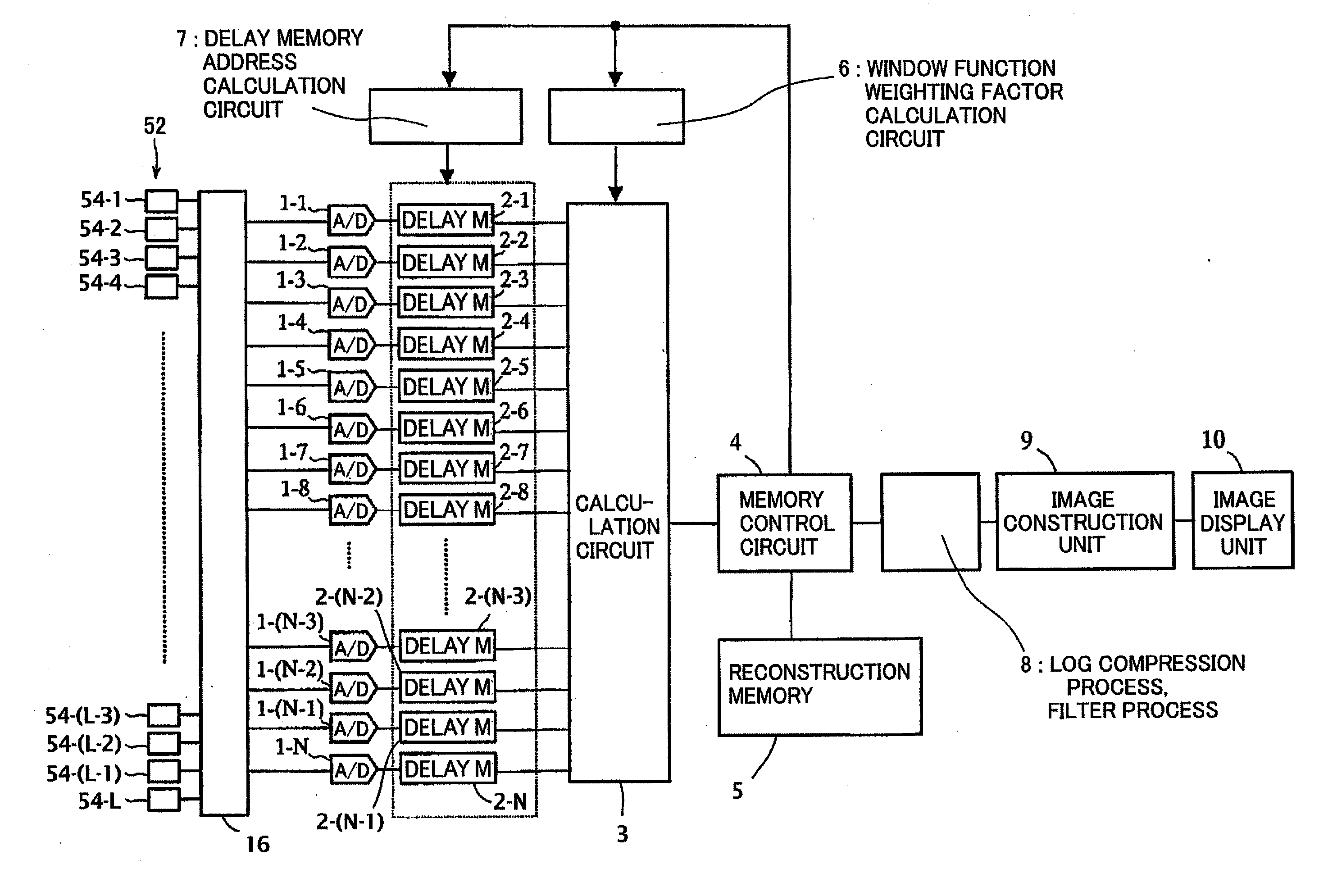
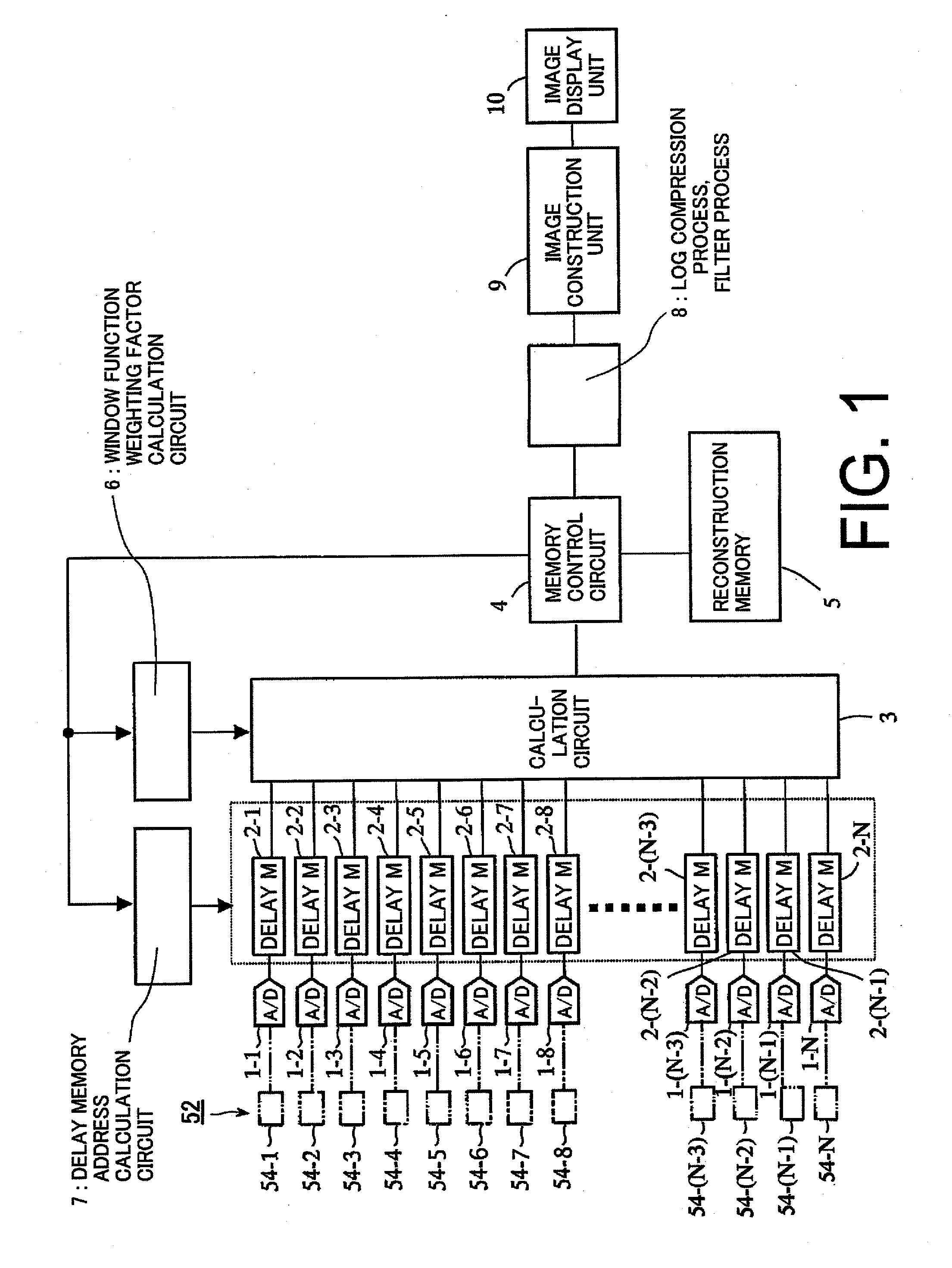
[0031]FIG. 1 is a view illustrating a received data processing apparatus of photoacoustic tomography according to a first embodiment of the present invention. In FIG. 1, the total number of channels of the received data processing apparatus of photoacoustic tomography is N.

[0032]The received data processing apparatus of photoacoustic tomography forms an image based an electrical signal obtained by irradiating a light on a specimen and receiving an acoustic wave generated from localized thermal expansion and contraction of the specimen as a result of the light irradiation.

[0033]The apparatus includes N A / D converters 1-1 to 1-N, N delay adjustment memories (DELAY M) 2-1 to 2-N, and a calculation circuit 3. In addition, the apparatus further includes a memory control circuit 4, a reconstruction memory 5, a window function weighting factor calculation circuit 6, a delay memory address calculation circuit 7, a signal processing block 8 (log compression process, filter process), an image...

second embodiment

[0068]FIG. 4 is a view illustrating a received data processing apparatus of photoacoustic tomography according to a second embodiment of the present invention. In FIG. 4, the number of acoustic wave detectors is L, and the total number of channels of the received data processing apparatus of photoacoustic tomography is N. In this case, L>N, that is, the number of acoustic wave detectors is larger than the total number of channels of the received data processing apparatus of photoacoustic tomography.

[0069]The received data processing apparatus of photoacoustic tomography includes N A / D converters 1-1 to 1-N, N delay adjustment memories (DELAY M) 2-1 to 2-N, and a calculation circuit 3. In addition, the apparatus further includes a memory control circuit 4, a reconstruction memory 5, a window function weighting factor calculation circuit 6, a delay memory address calculation circuit 7, a signal processing block 8 (log compression process, filter process) that performs a log compressio...

third embodiment

[0089]FIG. 6 is a view illustrating a received data processing apparatus of photoacoustic tomography according to a third embodiment of the present invention. In FIG. 6, the total number of channels of the received data processing apparatus of photoacoustic tomography is N.

[0090]The received data processing apparatus of photoacoustic tomography includes N A / D converters 1-1 to 1-N, addition averaging circuits 15-1 to 15-N, N delay adjustment memories (DELAY M) 2-1 to 2-N, and a calculation circuit 3. In addition, the apparatus further includes a memory control circuit 4, a reconstruction memory 5, a window function weighting factor calculation circuit 6, a delay memory address calculation circuit 7, a signal processing block 8 (log compression process, filter process), an image construction unit 9, and an image display unit 10.

[0091]The third embodiment is different from the first and second embodiments in that the addition averaging circuits 15-1 to 15-N as addition processing unit...


PUM


Abstract

There is provided a received data processing apparatus of photoacoustic tomography including a minimum constitution unit data composition unit that sequentially reads receiving digital signals from first storage units and composes minimum constitution unit data of the acoustic wave of the minimum constitution units by performing a delay-and-sum process; a second storage unit that stores the minimum constitution unit data of the entire region of the specimen; an image construction unit that constructs an image of the specimen based on the minimum constitution unit data stored in the second storage unit; and a control unit that sequentially stores the minimum constitution unit data calculated by the minimum constitution unit data composition unit in the second storage unit and reads the stored minimum constitution unit data of the entire region of the specimen to transmit the minimum constitution unit data to the image construction unit.

Description

TECHNICAL FIELD[0001]The present invention relates to a received data processing apparatus of photoacoustic tomography used for a photoacoustic tomography diagnostic apparatus, and more particularly, to a technique of generating image data based on an acoustic wave receiving signal.BACKGROUND ART[0002]Conventionally, it has been known that, when an electromagnetic wave is irradiated to a living body, an acoustic wave is generated due to a temperature increase and thermal expansion of an organism of the living body caused from the electromagnetic wave absorption of the living body. A technique (referred to as a photoacoustic tomography (PAT)) for visualizing an inner portion of the living body in a non-invasive manner by using the phenomenon has been attracting attention and employed in clinical sites using photoacoustic tomography diagnostic apparatuses.[0003]In the photoacoustic tomography diagnostic apparatus, light is irradiated to a specimen as a target, and an acoustic wave gen...

Claims


Application Information

Patent Timeline
Patent Type & Authority Applications(United States)
IPC IPC(8): G03B42/06
CPCA61B5/0073A61B8/483A61B8/13A61B5/0095A61B5/7225A61B5/7278
Inventor BABA, YOSHITAKAYODA, HARUOFUKUTANI, KAZUHIKO
Owner CANON KK
Why Eureka
Try Eureka