Liquid medication cartridge and inhaler using the cartridge

a technology of liquid medication and cartridge, which is applied in the field of liquid medication cartridge, can solve the problems of increase in weight, and difficulty in controlling the amount of ink filling, so as to improve the portability of the device, facilitate the filling operation, and reduce the effect of weigh

Inactive Publication Date: 2007-10-18
CANON KK
View PDF10 Cites 29 Cited by
  • Summary
  • Abstract
  • Description
  • Claims
  • Application Information

AI Technical Summary

Benefits of technology

[0012] 2. An inhaler is mostly used three times or more a day, so that it is absolutely necessary for the inhaler to be able to be carried about. In the case of a portable type inhaler, however, the ink suction mechanism leads to an increase in the weight, a complicated construction, and an increase in the cost of the device.
[0013] In view of the above problems, it is an object of the present invention to provide a liquid medication cartridge and an inhaler which are easily portable and are of simple construction.
[0016] According to the present invention, the liquid discharge portion is filled with the liquid medication by the filling means provided in the liquid medication cartridge, whereby the filling operation is completed easily and a state allowing discharge can be attained. Due to this arrangement, there is no need to provide a complicated filling means in the device to be used, and a reduction in weight can be achieved, which helps to contribute to an improvement in the portability of the device. Further, the liquid medication cartridge is of a simple construction and easy to manufacture. Further, it can retain the liquid medication in a hermetically sealed state like a medication container on the market, whereby it is also possible to secure a long preservation period for the liquid medication.

Problems solved by technology

In this process, it is rather difficult to control the ink filling amount by the negative pressure obtained by the pump, so that ink is sucked making allowance for a shortage of ink.
In the case in which an absorbing means, such as a sponge, is provided in the inhaler and in which the liquid medication is sucked and retained in the inhaler, the liquid medication retained is allowed to be oxidized, which leads to a problem in terms of hygiene and odor.
In the case of a portable type inhaler, however, the ink suction mechanism leads to an increase in the weight, a complicated construction, and an increase in the cost of the device.

Method used


Image

  • Liquid medication cartridge and inhaler using the cartridge
  • Liquid medication cartridge and inhaler using the cartridge
  • Liquid medication cartridge and inhaler using the cartridge

Examples


embodiment 1

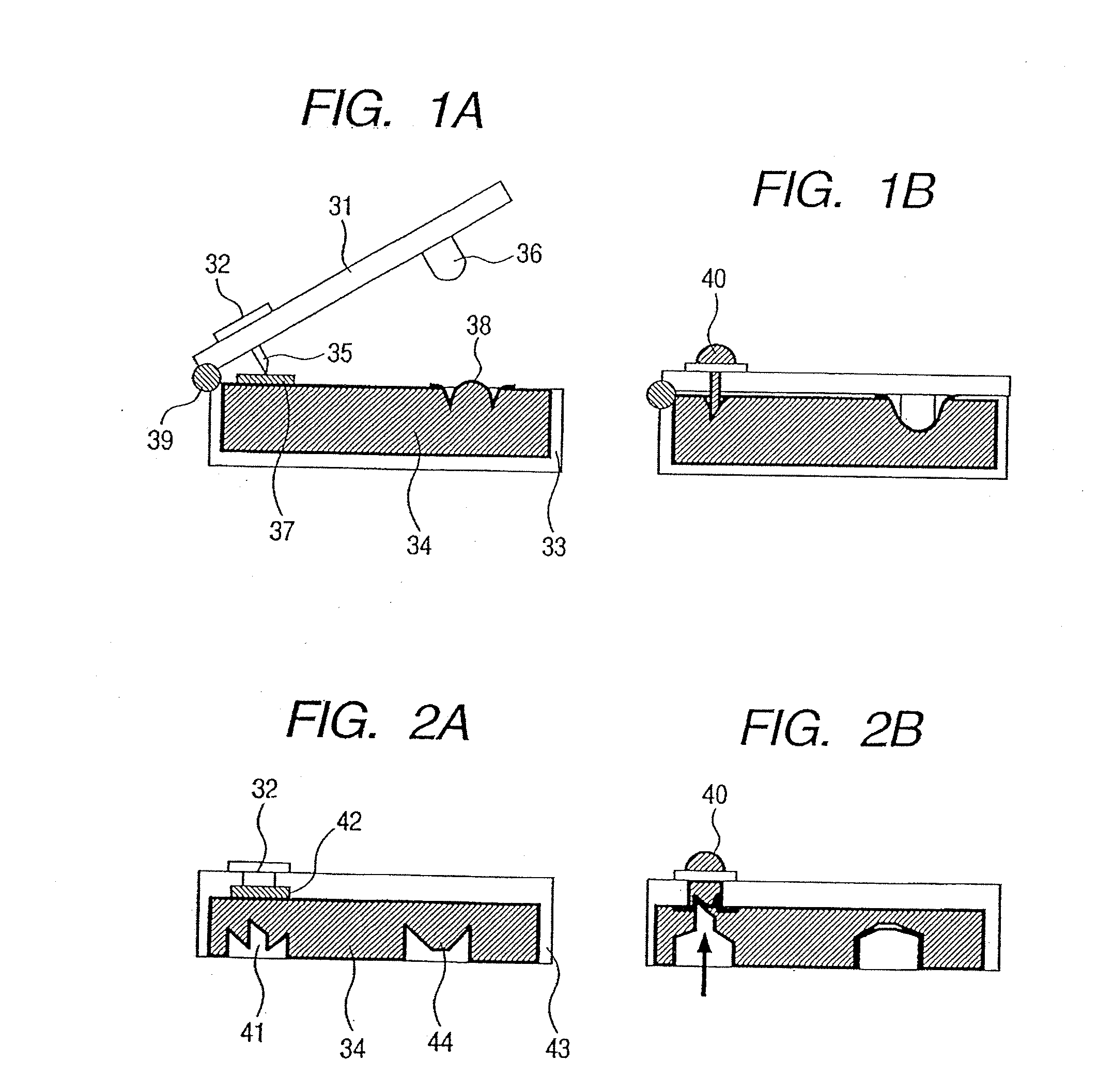
[0062]FIG. 1A is a sectional view of a liquid medication cartridge according to the present invention in which communicating operation and filling operation can be successively conducted by utilizing a hinge 39. The drawing shows the liquid medication cartridge in a state prior to establishment of communication and filling. FIG. 1B shows the liquid medication cartridge of the present invention in a state after establishment of communication and filling. A base plate 31 and a container 33 are integrated through the intermediation of the hinge 39. By molding them as a single part, it is possible to achieve a reduction in the number of parts and a reduction in cost. Provided on the base plate 31 are a liquid discharge portion 32 and a protrusion 36 constituting the filling means. The liquid discharge portion 32 communicates with a communicating means 35 within. The liquid medication is accommodated in the container 33, to which a film 37 and a deformable diaphragm 38 are mounted.

[0063...

embodiment 2

[0070]FIG. 2A is a sectional view of a liquid medication cartridge according to the present invention having the communicating means on the container side in a state prior to establishment of communication and filling. FIG. 2B is a sectional view of the liquid medication cartridge of the present invention in a state after establishment of communication and filling. The liquid medication in a container 43 and the liquid discharge portion 32 are isolated from each other through the intermediation of a film 42. As a communicating means 41, there is provided a component of a sharp configuration, for example, a needle-like component. The communicating means 41 and a diaphragm 44 are preferably formed of a soft material that can be deformed by pressurization by a finger, and they must be formed of a material that can maintain shape retention property. A material that can maintain shape retention property maintains its shape if no pressure is applied after its deformation by pressurization...

embodiment 3

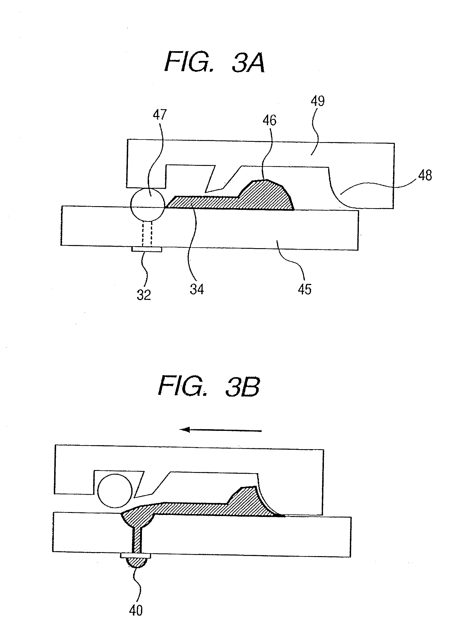
[0074]FIG. 3A is a sectional view of a liquid medication cartridge according to the present invention prior to establishment of communication and filling in a state in which the accommodating portion (container) and the liquid discharge portion, which originally communicate with each other, are disconnected from each other by a disconnecting means (pinch) 47. FIG. 3B is a sectional view of the same after establishment of communication and filling. A base plate 45 is equipped with a container 46 and the liquid discharge portion 32, and a slider 49 is slidably mounted to the base plate 45. The slider 49 is equipped with a means for pressing the disconnecting means 47 and a filling means 48 for effecting liquid medication filling. The liquid medication 34 is accommodated in the container 46, with the disconnecting means (pinch) 47 being pressed by the slider 49.

[0075] There are no particular limitations regarding the configuration and material of the disconnecting means (pinch) 47 as ...


PUM


Abstract

A liquid medication cartridge includes an accommodating portion for accommodating a liquid medication; a liquid discharge portion having a discharge port for discharging the liquid medication by using an ink jet technique, a communicating member for establishing communication between the accommodating portion and the liquid discharge portion and a filling member for filling the liquid discharge portion with the liquid medication.

Description

[0001] This application is a continuation of International Application No. PCT / JP2005 / 014361, filed Jul. 29, 2005, which claims the benefit of Japanese Patent Application No. 2004-225510, filed Aug. 2, 2004.BACKGROUND OF THE INVENTION [0002] 1. Field of the Invention [0003] The present invention relates to a liquid medication cartridge to be used in a device like an inhaler that discharges a medication as droplets. In particular, the present invention is suitable for use in an inhaler that discharges a liquid medication or a palatable substance, such as aroma or nicotine, in fine droplets for the user to inhale. [0004] 2. Related Background Art [0005] Conventionally, as liquid discharge head tanks for ink jet recording, a number of products have been proposed in which a mechanism for filling a liquid discharge head with ink is provided on the printer main body side. For example, JP 3311039 B discloses an ink jet recording apparatus which has a suction means, a suction cap, and a pro...

Claims


Application Information

Patent Timeline
Patent Type & Authority Applications(United States)
IPC IPC(8): A61M15/00
CPCA61M15/0065A61M15/025A61M2205/582A61M2016/0024A61M15/0066
Inventor KOBAYASHI, MASAYASEKINE, KENICHINOBUTANI, TOSHIYUKIIMAI, MITSURU
Owner CANON KK
Why Eureka
Try Eureka