Knee protection apparatus for vehicle occupant

a protection apparatus and vehicle occupant technology, applied in the direction of vehicular safety arrangments, pedestrian/occupant safety arrangements, vehicle components, etc., can solve the problems of airbags getting caught on such protruding and indentations, and reduce the chances reducing the chance of airbags being displaced or deformed, and increasing the cost of equipmen

Inactive Publication Date: 2006-04-06
TOYOTA JIDOSHA KK
View PDF24 Cites 31 Cited by
  • Summary
  • Abstract
  • Description
  • Claims
  • Application Information

AI Technical Summary

Benefits of technology

[0022] Also, it is preferable that an airbag case be provided, and the airbag and the airbag support be wrapped separately from each other and stored in the airbag case in such a way that the airbag support covers the airbag in the same case. With this arrangement, the airbag support holds the airbag, thus reducing the chances of the airbag being displaced or deformed.
[0023] Also, it is preferable that an airbag case for storing the airbag be provided, and the instrument side portion and the occupant side portion of the airbag support be wrapped separately and stored within the airbag case together with the airbag in such a way that, in the same case, the airbag wrapped is covered by the occupant side portion and the occupant side portion is covered by the instrument panel side portion. According to this construction, the airbag is supported by the support of the instrument panel side portion and the occupant side portion, reducing the chances of the airbag being displaced or deformed. Also, upon deployment of the airbag, the instrument panel side portion expands before the occupant side portion.
[0024] Also, it is preferable that one end portion of the airbag support be free and an anchor portion be provided at the same end. According to this construction, the expanding force of the airbag acts on the anchor portion so that the airbag support quickly expands with respect to the instrument panel. The anchor portion, for example, may be formed by applying sealing substance to the airbag support. In this case, the equipment for applying sealing substance to the airbag can be utilized to provide the anchor portion, and no additional equipment cost will therefore be required. Alternatively, the anchor portion may be formed by sewing one portion of the airbag support into a specific form. In this case, similarly, the equipment for sewing the airbag can be utilized to provide the anchor portion, and therefore no additional equipment cost will be required.
[0025] Also, it is preferable that the airbag support be provided with a friction reducer for reducing friction between the airbag support and the airbag. The friction reducer is provided to minimize or reduce the chances that the airbag support would get caught on the airbag upon deployment of the airbag. For example, the friction reducer may be formed by applying sealing substance to one side of the airbag support closer to the airbag. In this case, due to the sealing substance applied, the relative movements of the airbag and the airbag support can be made smoother. In this case, namely, the sealing substance can be utilized to reduce the friction between the airbag and the airbag support.
[0026] Also, it is preferable that the friction reducer be formed by a portion of the airbag support that is folded onto another portion (overlapped portions) of the airbag support. Due to the thus folded portion of the airbag support, the relative movements of the airbag and the airbag support are made smooth, and therefore the airbag support can smoothly expand with respect to the instrument panel. Also, the friction reducer may be formed through an arrangement of the airbag support and the airbag where a weave direction of base cloth of the airbag and a weave direction of base cloth of the airbag support are different This arrangement can be easily accomplished by appropriately setting the direction of cutting out the airbag support from its base cloth.
[0027] Also, it is preferable that the airbag support be attached at the bottom portion to the airbag while the top portion is free, and a peripheral length of a top side of the airbag support be longer than a peripheral length of a bottom side of the airbag support. According to this construction, even if there is a protrusion such as a steering column at a position corresponding to the top portion, the airbag support can appropriately expand while avoiding the protrusion.

Problems solved by technology

However, there is only a small space allowed for such deployment of the airbag, namely between the instrument panel and the knees of the occupant, and what is more, there are protrusions and indentations on the instrument panel side, such as those formed to provide good appearance of the instrument panel and formed by some related parts attached thereon, and it is therefore considered that the airbag would get caught on such protrusions and indentations when it expands as aforementioned.

Method used


Image

  • Knee protection apparatus for vehicle occupant
  • Knee protection apparatus for vehicle occupant
  • Knee protection apparatus for vehicle occupant

Examples


Embodiment Construction

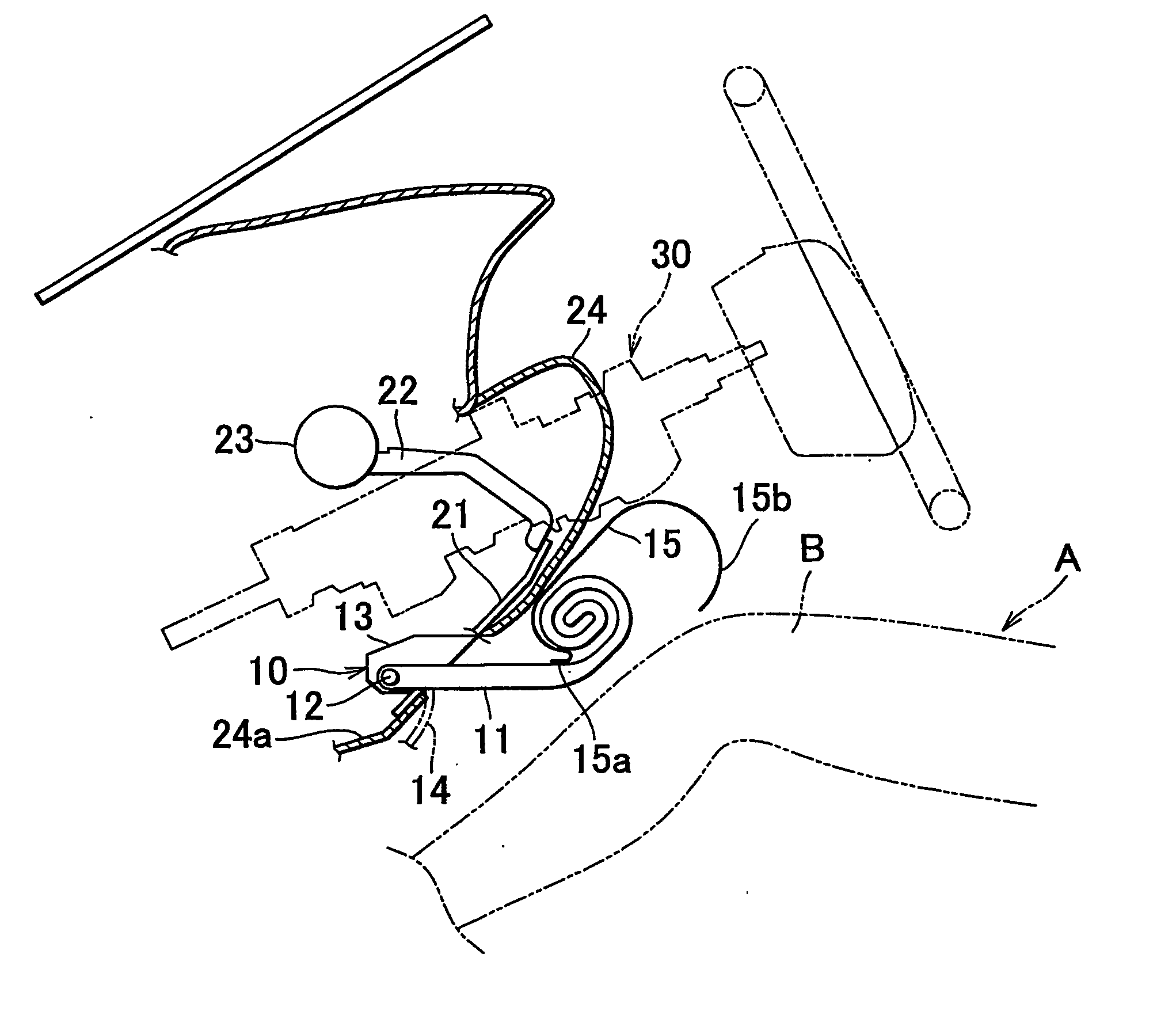
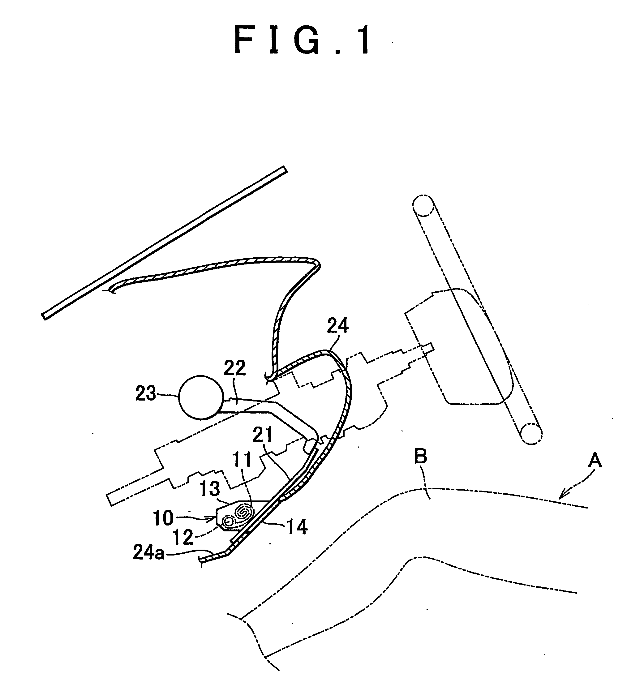
[0094] Hereinafter, exemplary embodiments of the present invention will be described with reference to the accompanying drawings. FIGS. 1 to 5 are views schematically showing the configuration of a knee protection apparatus for a vehicle occupant in accordance with one embodiment of the invention. According to this embodiment, a knee airbag module10 is fixed, at substantially the same height as knees B of an occupant A, to an instrument panel reinforcement 23 via a panel 21 and right and left brackets 22, and to a bottom portion 24A of an instrument panel 24 via the panel 21.

[0095] The knee airbag module 10 thus located in front of the knees B of the occupant A, includes an airbag 11, an inflator 12 for supplying gas to the airbag 11 upon collision of the vehicle, an airbag case 13 for storing the airbag 11 and the inflator 12, and an airbag cover 14 covering a rear opening 13a of the airbag case 13 (see FIG. 3).

[0096] The airbag 11 is formed of woven cloth (i.e., base cloth) sewn...


PUM


Abstract

A knee protection apparatus includes an airbag (11) and an airbag support (15) that is attached to the airbag. Upon deployment of the airbag (11), the airbag support together expands so as to cover the instrument panel and thus help the airbag smoothly expand.

Description

BACKGROUND OF THE INVENTION [0001] 1. Field of the Invention [0002] The present invention relates to a vehicle occupant protection apparatus, and more specifically, it relates to a knee protection apparatus for a vehicle occupant, which protects the occupant's knees by deploying an airbag stored in front of the knees using the gas from an inflator upon collision of the vehicle. [0003] 2. Description of the Related Art [0004] A known protection apparatus of this kind (e.g., Japanese Laid-open Patent Application No. 2002-249016) includes an airbag that is provided wrapped in front of the knees of an occupant and, when supplied with gas from an inflator, develops along the surface of the instrument panel to expand between the instrument panel and the occupant's knees. [0005] However, there is only a small space allowed for such deployment of the airbag, namely between the instrument panel and the knees of the occupant, and what is more, there are protrusions and indentations on the ins...

Claims


Application Information

Patent Timeline
Patent Type & Authority Applications(United States)
IPC IPC(8): B60R21/16B60R21/206B60R21/20
CPCB60R21/205B60R21/206B60R21/231B60R2021/23169B60R21/26B60R2021/0051B60R2021/01218B60R2021/23576B60R2021/23509
Inventor HAYAKAWA, TATSUYAYAMADA, EIICHIKONDO, HITOSHI
Owner TOYOTA JIDOSHA KK
Why Eureka
Try Eureka