Method for operating internal-combustion engines

A technology for internal combustion engines and diesel engines, applied in the field of internal combustion engines, can solve the problems of increased fuel consumption, difficulty in using diesel engines, and misfires, etc., and achieve the effect of eliminating the danger of transfer to the cylinder

Active Publication Date: 2008-09-03
VOLVO LASTVAGNAR AB
View PDF3 Cites 5 Cited by
  • Summary
  • Abstract
  • Description
  • Claims
  • Application Information

AI Technical Summary

Problems solved by technology

However, this method has some disadvantages: in the former case it leads to increased fuel consumption, while in the latter case, at least for diesel engines, it can lead to misfires and often requires new components
However, this variant is not easily applicable to diesel engines because when the piston is at top dead center (TDC) it is generally not possible to phase the camshaft to the same degree as when the valves are fully open, or at least open very far degree, because this degree will cause interference between the valve and the piston

Method used


Image

  • Method for operating internal-combustion engines
  • Method for operating internal-combustion engines
  • Method for operating internal-combustion engines

Examples


Embodiment Construction

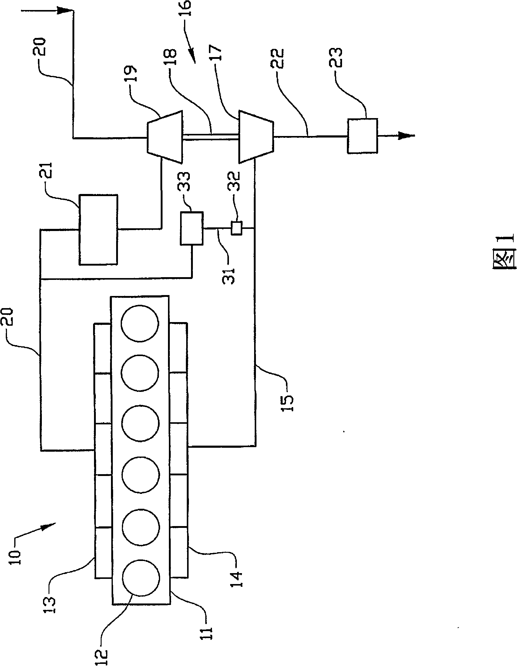
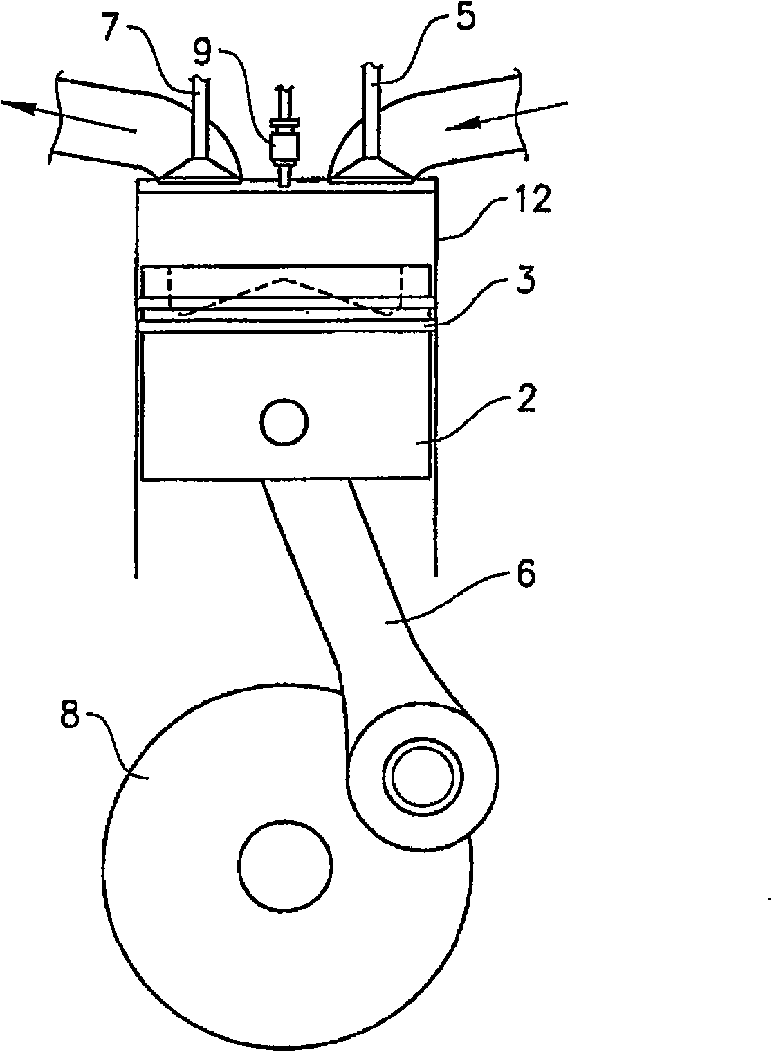
[0016] Figure 1 shows a schematic illustration of an internal combustion engine 10 in the form of a diesel engine. Internal combustion engine 10 includes an engine block 11 having six piston cylinders 12 together with an intake manifold 13 and an exhaust manifold 14 . The exhaust gas of the internal combustion engine is supplied via an exhaust line 15 to a turbine rotor 17 of a turbocharger unit 16 . The turbine shaft 18 drives a compressor wheel 19 of the turbocharger unit 16 , in this way an intake line 20 compresses the incoming air and delivers it to the intake manifold 13 via an air intercooler 21 . Fuel passes through fuel injector 9 (see figure 2 ) is supplied to each cylinder 12. The exhaust gas passing through the turbocharger unit 16 is forwarded via an exhaust line 22 to an exhaust gas aftertreatment device 23 . Furthermore, the internal combustion engine 10 has a system for returning exhaust gas to the intake side of the internal combustion engine 10 via a line ...


PUM


Abstract

The invention concerns a method for operating an internal combustion engine (10), said engine (10) comprising a plurality of cylinders (12) each of which having at least one valve of a first type, an inlet valve (5), and at least one valve of a second type, an exhaust valve (7), arranged in an end part of the cylinder (12), each of said cylinders (12) further having a piston (2) movably arranged therein, said piston (2) being adapted to reciprocate between an first end position (TDC) and a second end position (BDC), wherein the first end position (TDC) is located closer to the valves (5, 7) than the lower end position (BDC), said engine (10) being adapted to allow deactivation of at least one cylinder (12) by reducing its supply of fuel, said engine (10) further being adapted to allow varying opening times of the inlet valves (5) and / or the exhaust valves (7).; The invention is characterized in that the method comprises the step of extending the total opening time of at least one valve type (5, 7) of a deactivated cylinder (12) compared to the opening time of the same valve type (5, 7) when the cylinder (12) is active, said extension of the total opening time being performed such that at least one valve (5, 7) of said type is open at least partly both during a first engine stroke, wherein the piston (2) moves in a direction towards its second end position (BDC), as well as during a second consecutive engine stroke, wherein the piston (2) moves in a direction towards its first end position (TDC).

Description

technical field [0001] The invention relates to a method for operating an internal combustion engine operating with one or several cylinders deactivated. In particular, the invention relates to a method for operating a diesel engine operating with cylinders both active and deactivated. Background technique [0002] Exhaust gas aftertreatment systems for internal combustion engines usually need to operate within a certain temperature range. Occasionally, the operating state of the internal combustion engine is such that the exhaust gas temperature is too low for the exhaust gas aftertreatment system to work properly. Typically, this is a problem that arises during low load operating conditions of the diesel engine. [0003] One way to increase the exhaust gas temperature is to use a gas restrictor placed on the exhaust side to increase the engine load, or a gas restrictor placed on the intake side to reduce the amount of air entering the cylinder. However, this method has ...

Claims


Application Information

Patent Timeline
Patent Type & Authority Applications(China)
IPC IPC(8): F02D13/06
CPCF02D13/06Y02T10/18F02M25/0707F02D13/0207F02D13/0273F02M25/0727F02D17/02F02B3/06F02M26/05F02M26/23Y02T10/12
Inventor 佩尔·佩尔松
Owner VOLVO LASTVAGNAR AB
Why Eureka
Try Eureka