Control system of compression-ignition engine

a control system and compression ignition technology, applied in the direction of electric control, ignition automatic control, machines/engines, etc., can solve the problems of increasing the in-cylinder pressure and the in-cylinder temperature resulting from the si combustion, and the engine which operates by a suitable hcci combustion has not yet been put into practical use, so as to improve the thermal efficiency and reduce the si ratio , the effect of increasing the ci combustion ratio

Active Publication Date: 2019-11-28
MAZDA MOTOR CORP
View PDF0 Cites 5 Cited by
  • Summary
  • Abstract
  • Description
  • Claims
  • Application Information

AI Technical Summary

Benefits of technology

[0026]By adjusting the ignition timing so as to realize the SPCCI combustion conforming to the target SI ratio, for example, the ratio of the CI combustion can be increased (i.e., the SI ratio is lowered). This leads to improving thermal efficiency by the SPCCI combustion as much as possible.

Problems solved by technology

However, it is necessary to solve various problems of automobile engines which require an improvement in thermal efficiency, and engines which operate by a suitable HCCI combustion have not yet been put into practical use.
That is, although the engines mounted on automobiles vary largely in the operating state and the environmental condition, the HCCI combustion has a problem in which a combustion start timing of the mixture gas (timing at which the mixture gas self-ignites) changes largely by external factors, such as temperature, and also has a problem in which control during a transition operation in which load changes suddenly is difficult.
Therefore, if the flame propagation of the SI combustion is not stable, increasing amounts of the in-cylinder pressure and the in-cylinder temperature resulting from the SI combustion decreases, and it becomes difficult to raise the in-cylinder temperature to the ignition temperature.
However, in such an A / F lean environment, it becomes difficult to stabilize the flame propagation of the SI combustion.

Method used


Image

  • Control system of compression-ignition engine
  • Control system of compression-ignition engine
  • Control system of compression-ignition engine

Examples


Embodiment Construction

(1) Entire Configuration of Engine

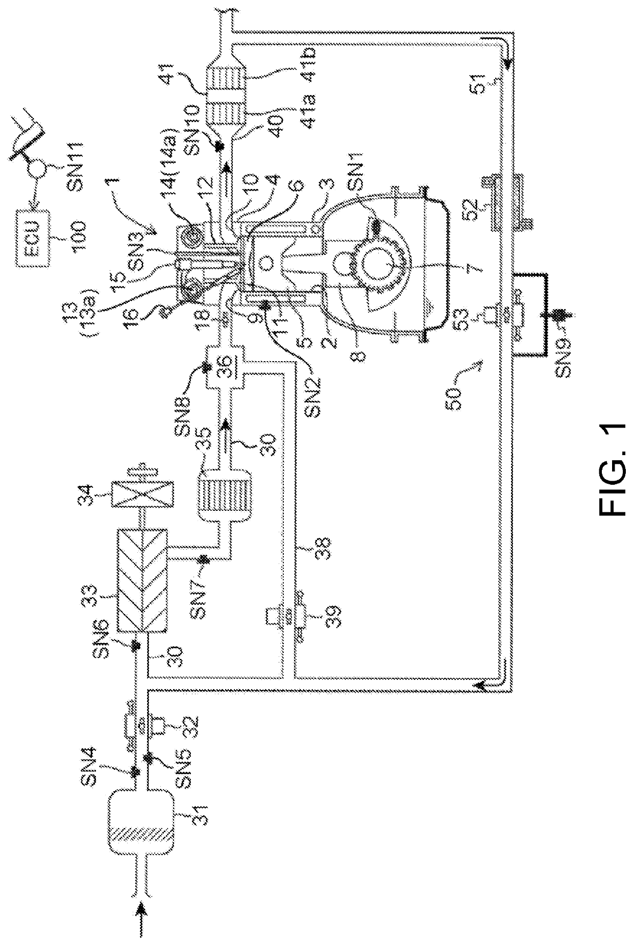
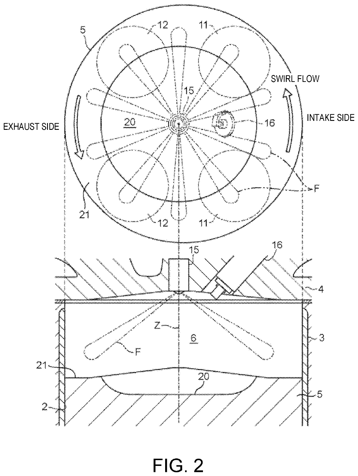
[0042]FIGS. 1 and 2 are views illustrating a desirable embodiment of a compression-ignition engine (hereinafter, simply referred to as “the engine”) to which a control system of the present disclosure is applied. An engine illustrated in these figures is a four-cycle gasoline direct-injection engine mounted on a vehicle, as a power source for propulsion, and includes an engine body 1, an intake passage 30 through which intake air introduced into the engine body 1 flows, an exhaust passage 40 through which exhaust gas discharged from the engine body 1 flows, and an external exhaust gas recirculation (EGR) system 50 which recirculates to the intake passage 30 part of the exhaust gas flowing through the exhaust passage 40.

[0043]The engine body 1 includes a cylinder block 3 where a cylinder 2 is formed therein, a cylinder head 4 attached to an upper surface of the cylinder block 3 so as to cover the cylinder 2 from above, and a piston 5 reciprocatably i...


PUM


Abstract

A control system of a compression-ignition engine which performs SPCCI combustion in which mixture gas is ignited with a spark plug to be partially combusted by SI combustion and the rest of mixture gas self-ignites to be combusted by CI combustion, is provided. When the engine is operated at least in a given first operating range, a controller of the device controls a variable intake mechanism so that an A/F lean environment where an air-fuel ratio in a cylinder becomes higher than a stoichiometric air-fuel ratio is formed, while causing the spark plug to perform spark ignition at a given timing so that the mixture gas combusts by SPCCI combustion, and controls so that, under the same engine load condition, an intake valve close timing is more retarded as the engine speed decreases, within a range where an amount of air inside the cylinder decreases by retarding the close timing.

Description

TECHNICAL FIELD[0001]The present disclosure relates to a control system of a compression-ignition engine, which is capable of carrying out a partial compression-ignition combustion in which a mixture gas within a cylinder is partially combusted by spark-ignition (SI combustion) and then the remaining mixture gas is combusted by self-ignition (CI combustion).BACKGROUND OF THE DISCLOSURE[0002]In recent years, Homogeneous-Charge Compression Ignition (HCCI) combustion in which a gasoline fuel mixed with air combusts by self-ignition inside a fully-compressed combustion chamber has attracted attention. Since the HCCI combustion is a form in which the mixture gas combusts simultaneously without flame propagation, the combusting speed of the mixture gas is faster than the SI combustion (jump-spark-ignition combustion) which is adopted by normal gasoline engines. Therefore, it is said that the HCCI combustion is very advantageous in terms of thermal efficiency. However, it is necessary to s...

Claims


Application Information

Patent Timeline
Patent Type & Authority Applications(United States)
IPC IPC(8): F02P5/04F02P5/15F02D13/02F02D41/00F02D13/06
CPCF02D13/0234F02D13/0215F02D41/0007F02D41/1475F02D41/3041F02D41/0087F02B31/085F02D13/0219F02D13/06F02D2200/101F02P5/045F02P5/1502F01L2800/13F01L1/34F02D13/0261F02B1/08F02B1/10
Inventor SUEOKA, MASANARIINOUE, ATSUSHIMARUYAMA, KEIJIOHURA, TAKUYANISHIDA, TOMOHIROKAWAI, YUSUKECHIKADA, TETSUYATOKUNAGA, TATSUHIRO
Owner MAZDA MOTOR CORP
Why Eureka
Try Eureka