Apparatus and method for determining objective refraction using wavefront sensing

a wavefront sensing and objective technology, applied in the field of apparatus for determining the refraction of the eye, can solve the problems of poor vision quality of patients, poor quality of vision of patients, and selection of less than optimum prescriptions

Inactive Publication Date: 2007-05-17
ESSILOR INT CIE GEN DOPTIQUE
View PDF58 Cites 14 Cited by
  • Summary
  • Abstract
  • Description
  • Claims
  • Application Information

AI Technical Summary

Problems solved by technology

Unfortunately, as recognized herein the patient can become fatigued during the process and / or misjudge the vision afforded by the various lenses.
This can lead to the selection of a less than optimum prescription.
Moreover, some patients, such as a very ill or a very young patient, might not be capable of articulating the quality of vision the various lenses afford the patient.
Objective methods of determining the patient's refraction errors have been proposed, but these other methods introduce further complications that are not present when using phoropters.
However, the method does not provide sufficient accuracy for prescribing spectacle lenses.
Unfortunately, the measurement outcome often differs from the patient's ideal prescription.
Moreover, both retinoscopy and autorefraction fail to account for the accommodation effect of the patient, that is, for the propensity of a patient to alter his or her focus or sight to make the best of the vision test.
Examination results that include patient accommodation effects are inaccurate for prescribing spectacle lenses.
Another limitation of the autorefractor is that the examiner has no control over which lens is to be used in test.
The result is that repeated measurements are likely to provide different results for the same eye from the same patient, which results in laborious and time consuming tests and retests when using the device to finalize a prescription.

Method used


Image

  • Apparatus and method for determining objective refraction using wavefront sensing
  • Apparatus and method for determining objective refraction using wavefront sensing
  • Apparatus and method for determining objective refraction using wavefront sensing

Examples


Embodiment Construction

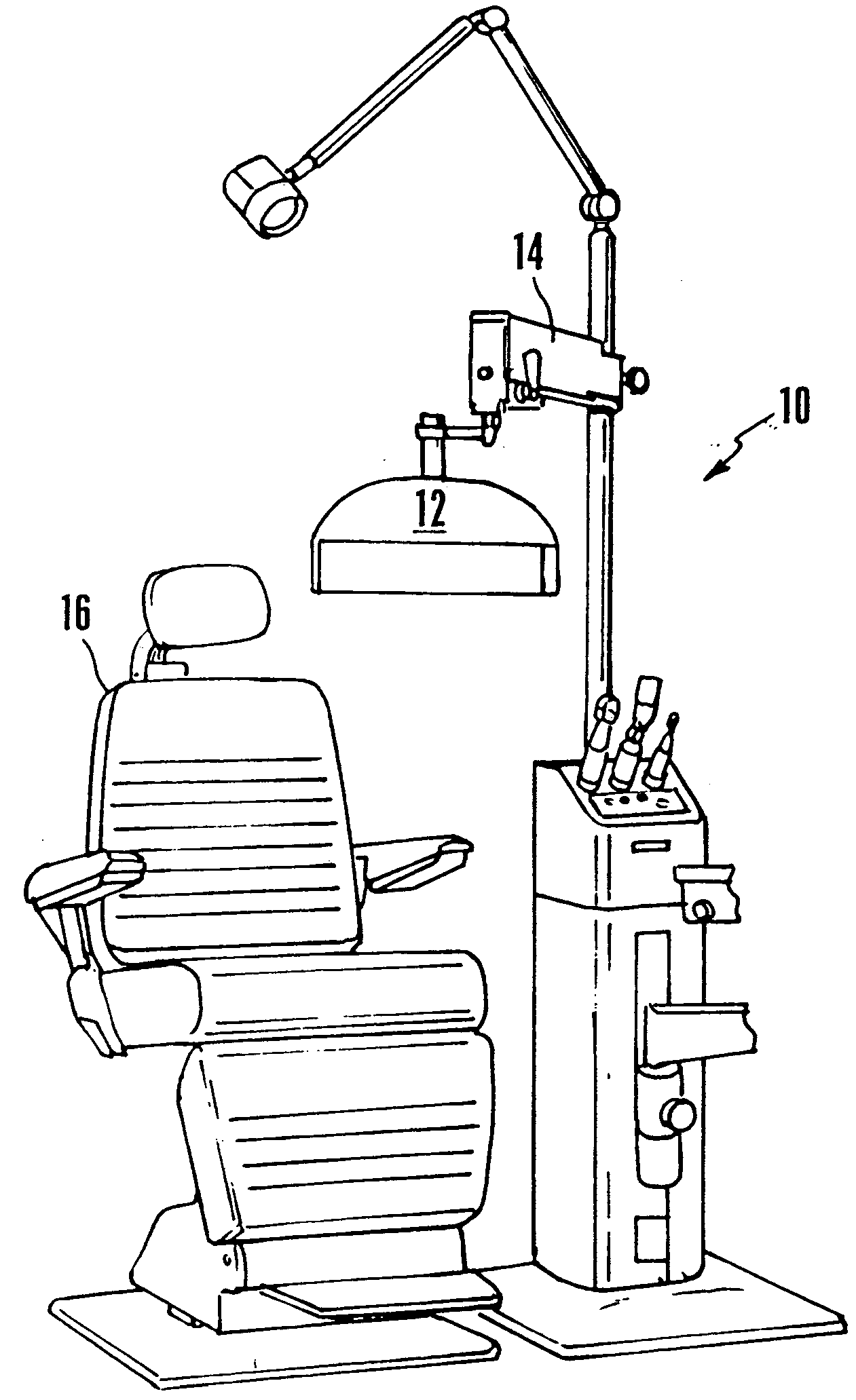
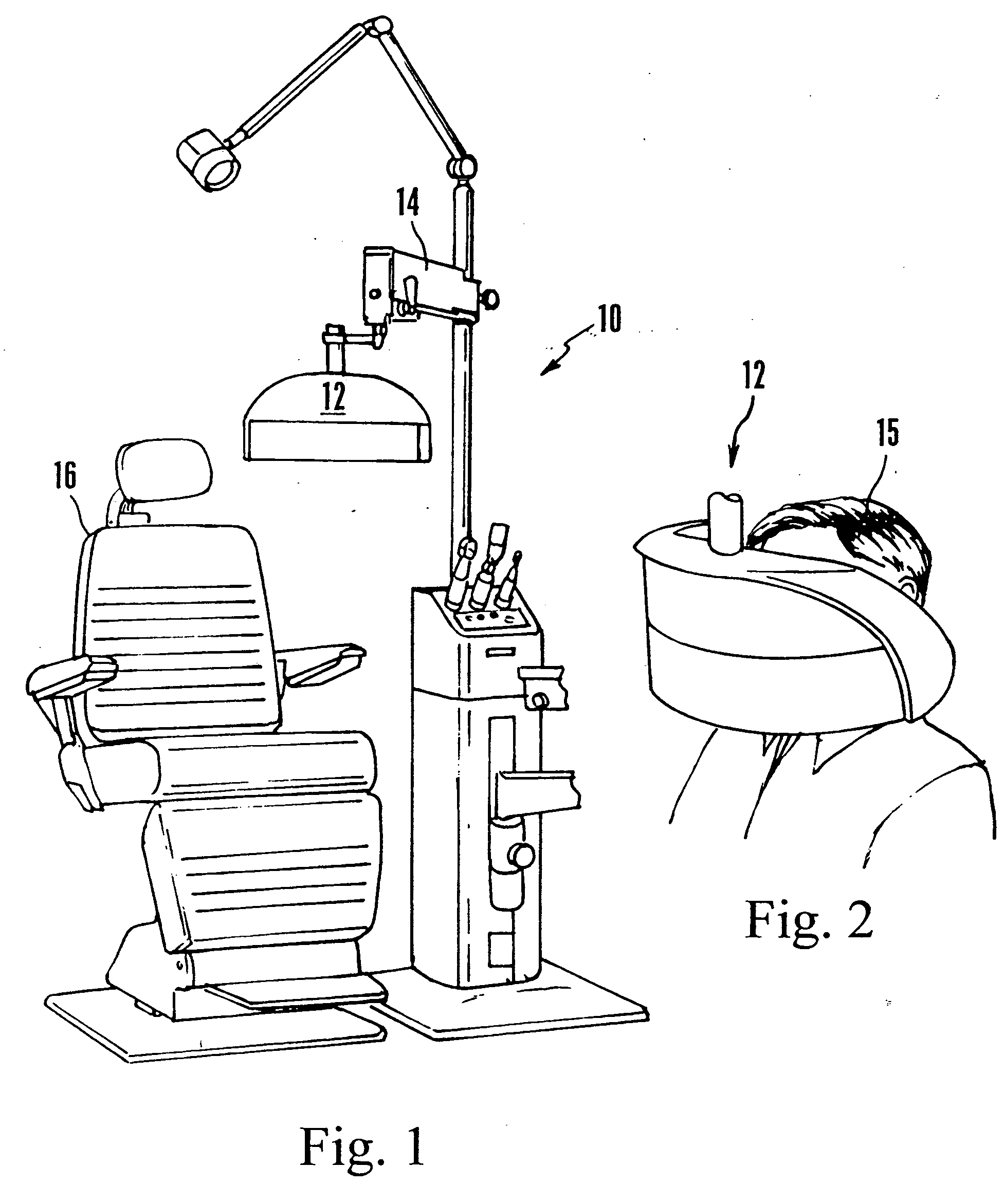
[0024] Referring initially to FIGS. 1 and 2, an apparatus of the present invention is shown, generally designated 10, and includes a housing 12 that can be mounted on a movable stand 14 for positioning the housing 12 in front of a patient 15 who might sit in an examination chair 16. As can be appreciated in cross-reference to FIGS. 1 and 2, the patient 15 can position his or her head against the housing 12. Alternatively, the housing 12 can be supported on the head of the patient 15 and / or be suspended from a flexible overhanging arm which may be attached to a stand, to provide weight balance and to facilitate mounting and dismounting of the head mounted-apparatus. Or, the apparatus of the present invention can be co-mounted with a conventional phoropter (not shown), in which case the test lenses of the present invention can be established by the lenses of the conventional phoropter.

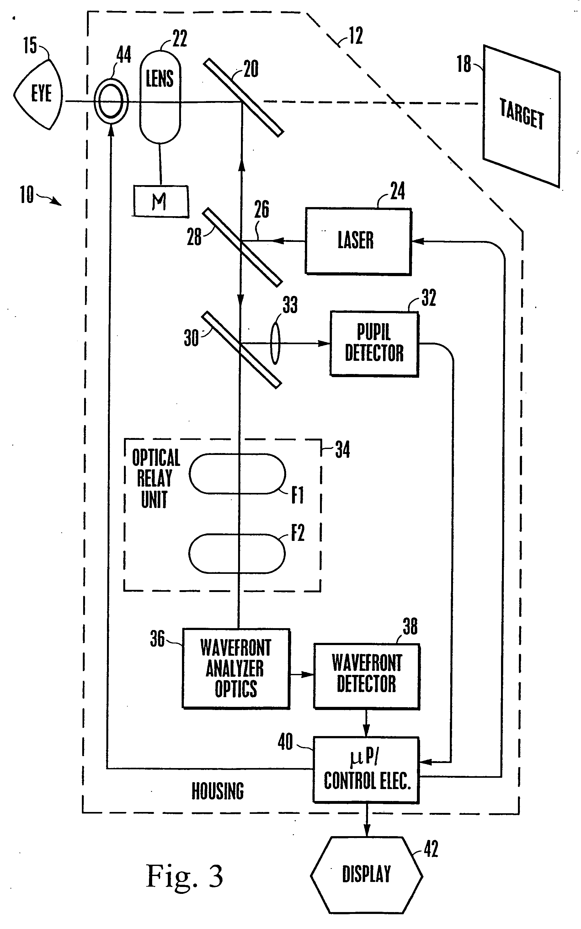
[0025] Now referring to FIG. 3, the patient 15 can look through the housing 12 to a target 18, such ...


PUM


Abstract

An apparatus for determining the objective refraction of a patient's eye includes a transparent window and a wavefront measurement device that determines aberrations in a return beam from the patient's eye after the beam passes through a corrective test lens in the apparatus. The wavefront measurement device outputs an instant display representative of the quality of vision afforded the patient through the test lens. The display can be a representation of a Snellen chart, convoluted with the optical characteristics of the patient's vision, an overall quality of vision scale or the optical contrast function, all based on the wavefront measurements of the patient's eye. The examiner may use the display information to conduct a refraction examination and other vision tests without the subjective response from the patient.

Description

CROSS-REFERENCE TO RELATED APPLICATIONS [0001] This application is a continuation of U.S. Ser. No. 10 / 653,552 filed Sep. 2, 2003, which is a continuation of PCT / US2003 / 004921, filed on Feb. 13, 2003, which is a continuation of U.S. Ser. No. 10 / 076,218 filed Feb. 13, 2002, now U.S. Pat. No. 6,761,454. The contents of these applications are incorporated herein by reference.FIELD OF THE INVENTION [0002] The present invention relates generally to methods and apparatus for determining a person's visual characteristics, and more particularly to apparatus for determining the refraction of the eye. BACKGROUND [0003] Phoropters are apparatus used by optometrists to determine a patient's visual characteristics, so that proper eye diagnoses can be made and eyewear can be prescribed. In conventional phoropters, a patient looks through the phoropter, in which various test lenses are disposed, at a target eye chart, referred to as a “Snellen chart”, while an optometrist moves the test corrective ...

Claims


Application Information

Patent Timeline
Patent Type & Authority Applications(United States)
IPC IPC(8): A61B3/14A61B3/032A61B3/103
CPCA61B3/032A61B3/1015
Inventor LAI, SHUI T.DREHER, ANDREAS W.
Owner ESSILOR INT CIE GEN DOPTIQUE
Why Eureka
Try Eureka