Supercharge Your Innovation With Domain-Expert AI Agents!

Compression snap electrical connector

a technology of electrical connectors and snaps, applied in the direction of coupling device details, coupling device connections, contact members penetrating/cutting insulation/cable strands, etc., can solve the problem of less than optimal physical and electrical connection

Inactive Publication Date: 2007-05-24
CENTPIN TECH
View PDF23 Cites 13 Cited by
  • Summary
  • Abstract
  • Description
  • Claims
  • Application Information

AI Technical Summary

Benefits of technology

[0009] In a further aspect of the invention, an electrical connector is provided which has a connector body with a bore and at least one groove therein, and a cap. The bore is defined by a sidewall which includes a beveled portion that is sloped so as to be more constricted as one proceeds in an axial dire

Problems solved by technology

But helical twisting motions of a multistranded conductor as it is being connected often torsionally stress the metallic strands sought to be connected, resulting in a less than optimum physical and electrical connection.

Method used


Image

  • Compression snap electrical connector
  • Compression snap electrical connector
  • Compression snap electrical connector

Examples


Embodiment Construction

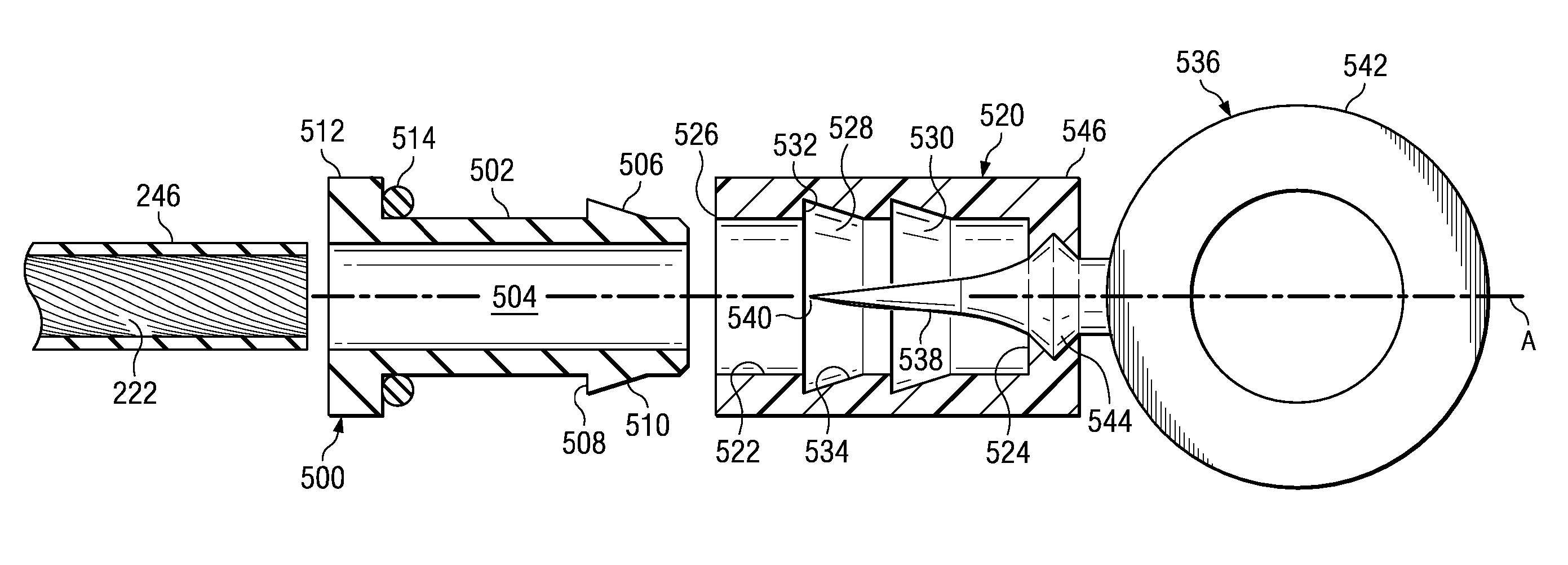
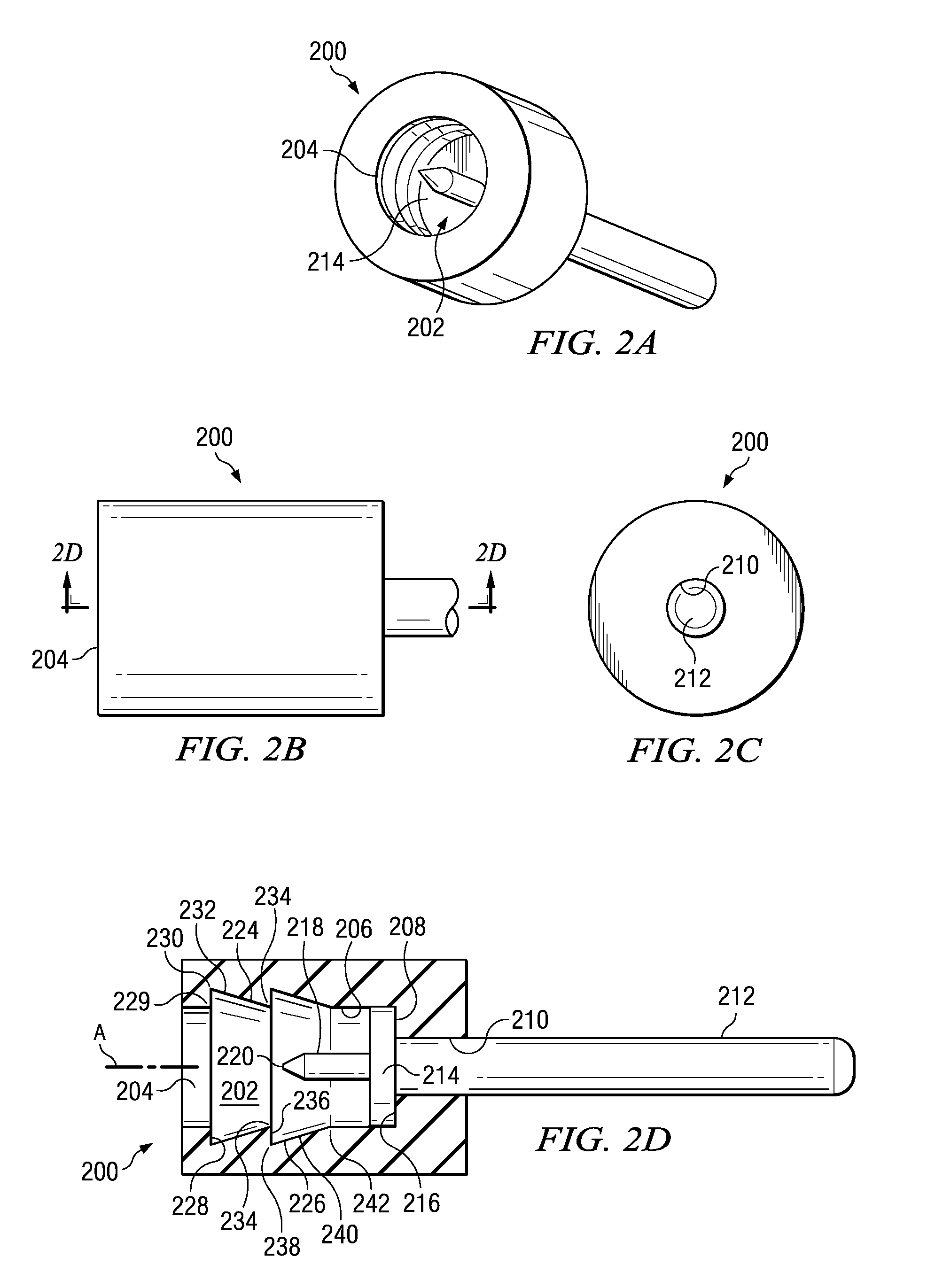
[0026] Referring first to FIGS. 1A-1D and 2A-2D, in a first embodiment of the invention, a connector body 200 has a generally cylindrical external shape. Throughout these illustrated embodiments, it should be understood that the body 200 and its analogs can be plastic, metal, or any other suitable material; body 200 does not have to be conductive. The body 200 has a bore 202 with an open end 204 and a generally cylindrical interior sidewall 206 which terminates in a bottom 208. The body 200 and the bore 202 are conveniently formed around an axis A. The body 200 preferably should be formed of a material that is somewhat elastic, so that it will stretch slightly and snap back during stages of insertion of the cap and conductor into the bore 202, as will be later described. But the body 200 should not be so elastic that the connection will easily fail because of the cap being pulled back out of the connector body.

[0027] The bottom 208 of the bore 202 has a central hole 210 through whi...


PUM

PropertyMeasurementUnit
Diameteraaaaaaaaaa
Electrical conductoraaaaaaaaaa

Abstract

An electrical connector has a connector body with a bore and a cap through which a stranded insulated conductor is threaded. A ridge in the external surface of the cap engages with at least one groove in the bore to secure the conductor in place. Preferably, there are at least two such grooves in the bore at different axial positions, and the cap is axially advanced from one such groove to another one farther inside the bore to effect full physical and electrical connection.

Description

RELATED APPLICATIONS [0001] This application is a division of copending U.S. patent application Ser. No. 11 / 420,646 filed 26 May 2006, which application is assigned to the assignee hereof and whose disclosure is completely incorporated by reference herein.BACKGROUND OF THE INVENTION [0002] There are many electrical connectors which are known from the published prior art or the marketplace. These connectors seek to connect together electrical conductors without soldering and often without the use of tools. Connectors exist for multistranded insulated wires or cables as well as coaxial cables. [0003] Several such connectors are sold by Swenco Products, Inc. under the mark POSI-LOCK®. Many of these connectors are illustrated in U.S. Pat. Nos. 5,228,875; 5,868,589; 6,358,103 B1; 6,494,753 B1; 6,568,952 B1; 6,692,313 B1; 6,695,653 B1; 6,814,630 B1; 6,830,491 B1; 6,851,966 B1; 6,866,550 B1; and U.S. Patent Application Pub. No. US2004 / 0192121 A1. These connectors usually require stripping ...

Claims


Application Information

Patent Timeline
IPC IPC(8): H01R11/20
CPCH01R4/5033H01R4/5083Y10T29/49174H01R13/5202H01R13/5205H01R11/12
Inventor HANKS, RIP
Owner CENTPIN TECH
Features
  • R&D
  • Intellectual Property
  • Life Sciences
  • Materials
  • Tech Scout
  • Unparalleled Data Quality
  • Higher Quality Content
  • 60% Fewer Hallucinations
Learn More