Golf club head

Inactive Publication Date: 2007-05-24
YONEX CO LTD
View PDF12 Cites 101 Cited by
  • Summary
  • Abstract
  • Description
  • Claims
  • Application Information

AI Technical Summary

Benefits of technology

[0011] When the golf club head strikes a golf ball, the face section is deformed to bulge backward and to compress the closed void section of the reinforced fiber member therebehind. With the compression force, the

Problems solved by technology

However, the deformation of the metallic striking face part at the time of striking the ball is very small.
The repulsi

Method used


Image

  • Golf club head
  • Golf club head
  • Golf club head

Examples


Embodiment Construction

[0020] Hereinafter, a description is given of preferred embodiments of the present invention with reference to the accompanying drawings.

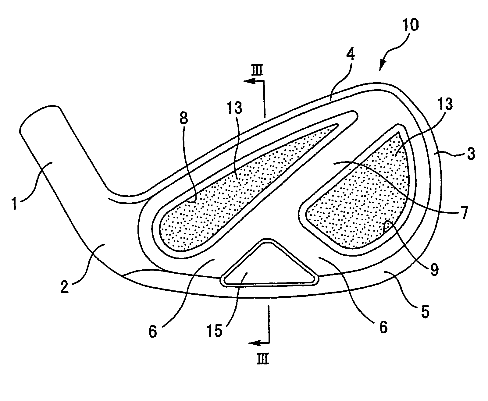
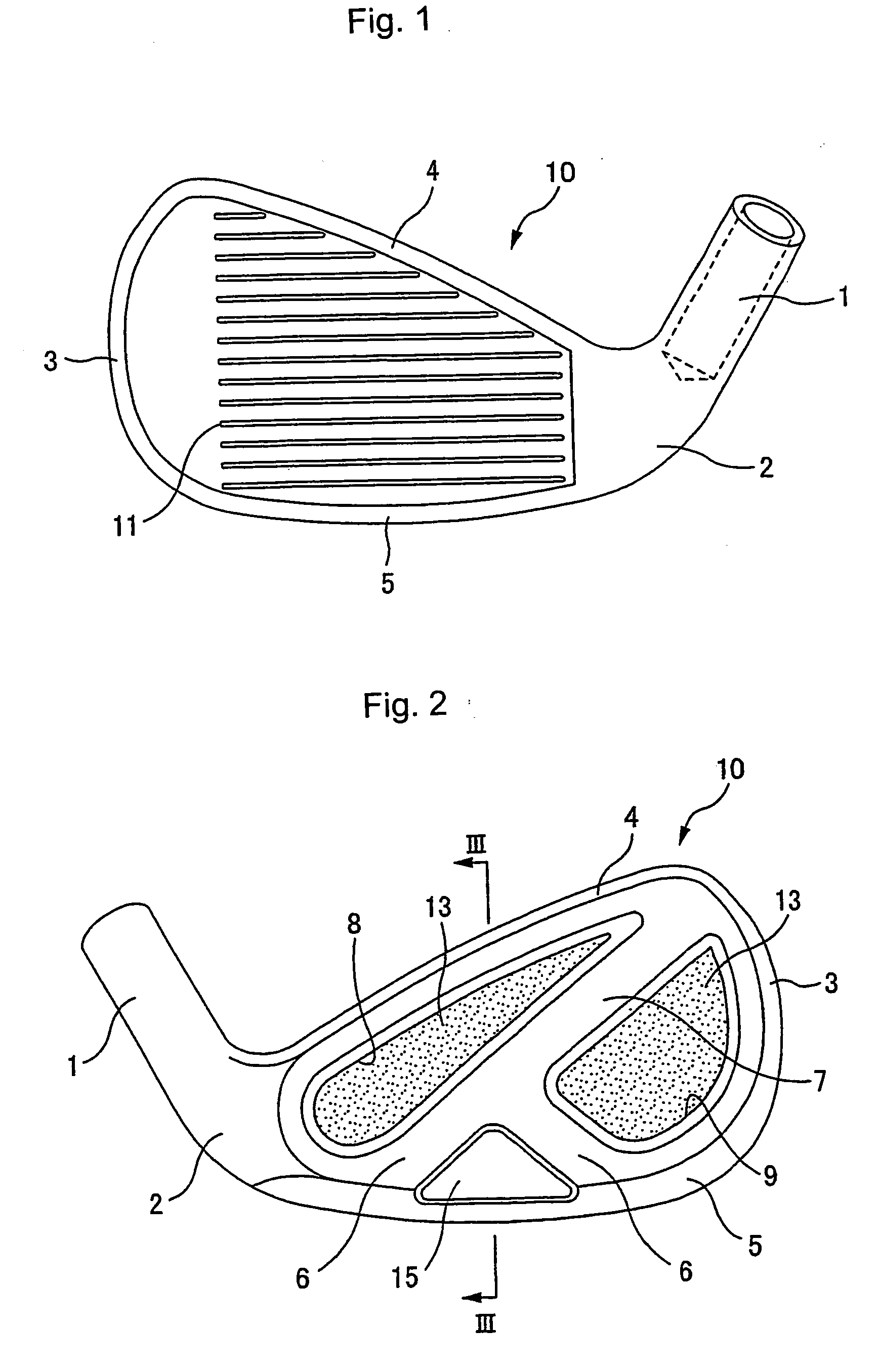
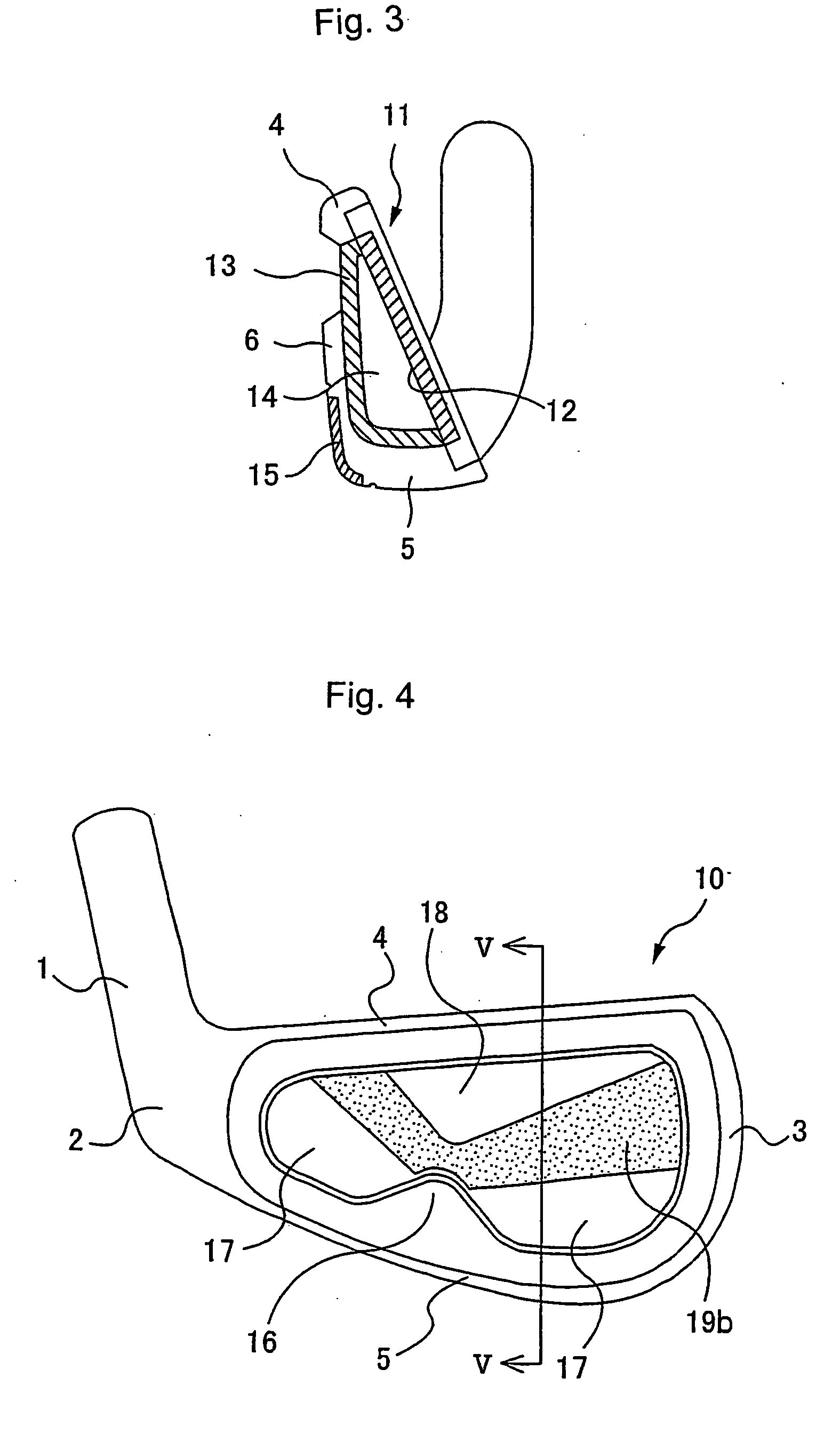
[0021] FIGS. 1 to 3 show an iron golf club head according to a preferred embodiment of the present invention. In the front view of FIG. 1, a head body 10 of the club head is formed in a frame-shape composed of a hosel section 1, into which a shaft (not shown) is inserted, a heel section 2 under the hosel section 1, a circular arc-shaped toe section 3, a belt-shaped upper edge section 4 connecting the upper ends of the heel section 2 and of the toe section 3, and a sole 5 connecting the lower ends of the heel section 2 and of the toe section 3.

[0022] As shown in FIGS. 2 and 3, on the back side of the head body 10, a chevron-shaped extension section 6 and a belt-shaped section 7 are provided. The chevron-shaped extension section 6 protrudes upward from the rear edge of the sole section 5 substantially at a right angle thereto. The belt-shaped exten...


PUM


Abstract

A metallic frame-shaped iron head body is composed of a heel section, a toe section, an upper edge section connecting superior ends of the heel section and of the toe section, and a sole section. On a front face of the head body, a metallic thin-walled face section having a high coefficient of restitution is provided. The head body includes rear wall sections spaced apart from the face section and extending upward from a rear end of the sole section. A reinforced fiber member is placed in an area surrounded by the face section, the sole section, and the rear wall sections. This reinforced fiber member abuts on a back of the face section to form a closed hollow void section, and apart of a back of the reinforced fiber member is supported on the rear wall sections.

Description

CROSS REFERENCE TO RELATED APPLICATION [0001] This application is based upon and claims the benefit of priority from prior Japanese Patent Application No. 2003-415114, filed on Dec. 12, 2003; the entire contents of which are incorporated herein by reference.BACKGROUND OF THE INVENTION [0002] 1. Field of the Invention [0003] The present invention relates to a golf club head, and more specifically, relates to an iron-type golf club head composed of a metallic head body and a reinforced fiber member. [0004] 2. Description of the Related Art [0005] In publicly-known conventional iron-type golf club heads each composed of a metallic head body and a reinforced fiber member, a metallic striking face part is formed to be thin-walled, and a thick-walled fiber reinforced plastic layer is attached to or filled in the back of the striking face part as shown in Japanese Patent publications No. 65708 / 1992 and No. 88153 / 1993 and Japanese Patent Laid-open publication No. 173513 / 1997. [0006] Such go...

Claims


Application Information

Patent Timeline
IPC IPC(8): A63B53/00A63B53/04
CPCA63B53/0475A63B2053/0416A63B2053/0425A63B53/047A63B2209/02A63B2209/023A63B2209/00A63B53/0425A63B53/0416
Inventor YONEYAMA, KOSAKU
Owner YONEX CO LTD
Why Eureka
Try Eureka