
Information display system having graphical user interface switchingly controlling information display on display screen

Inactive Publication Date: 2007-05-24
FUJITSU LTD
View PDF28 Cites 17 Cited by
  • Summary
  • Abstract
  • Description
  • Claims
  • Application Information

AI Technical Summary

Benefits of technology

[0018] It is a primary object of the present invention, which was devised to obviate the problems peculiar to the prior art, to provide an information display system capable of efficiently browsing items of information related by links.
[0020] It is a further object to provide a graphical user interface for displaying plural items of information by readily switching the information.

Problems solved by technology

In the conventional display system displays the information to be browsed in the single display area and is therefore very hard to use in the following applications in some cases.
(2) The user is unable to compare two contents on the conventional one browser.
(3) When the user attempts to arrange plural items of information in the same screen dimensions, it takes a labor to adjust the screen dimensions of the browsers opened separately and arrange them.
The title characters do not, however, enable the user to sufficiently grasp contents of that page.
The user is therefore unable to accurately find out the desired page in the history.
The user is, however, unable to browse a plurality of registered pages at one time.
(6) When the user attempts to monitor an image and a picture on the page updated periodically, e.g., at an interval of several minutes, if the user is tempted to browse other page until the former page is updated, there might be a possibility in which the user fails to see the updating of the former image and the picture that should be monitored.
Therefore, the user is required to refer to the hierarchy-structured list in order to select the desired page, which is complicated in terms of operation.
Hence, there arises a problem inherent in this operation method, wherein the operation is hard to persons advanced in age and children or persons somewhat disable in their hands.

Method used


Image

  • Information display system having graphical user interface switchingly controlling information display on display screen
  • Information display system having graphical user interface switchingly controlling information display on display screen
  • Information display system having graphical user interface switchingly controlling information display on display screen

Examples


first embodiment

[0069] A first embodiment of the present invention will hereinafter be described in conjunction with FIGS. 1 through 15.

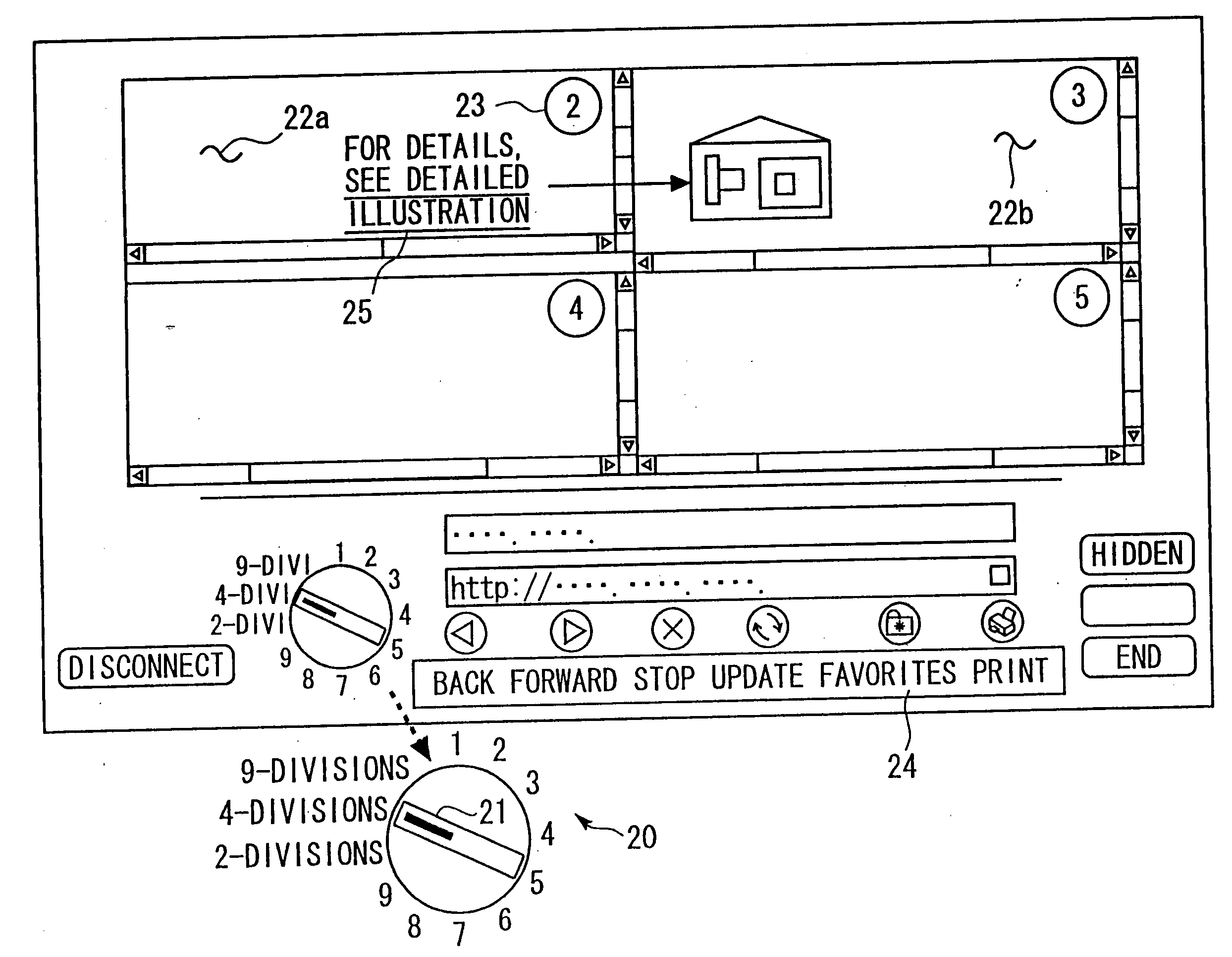
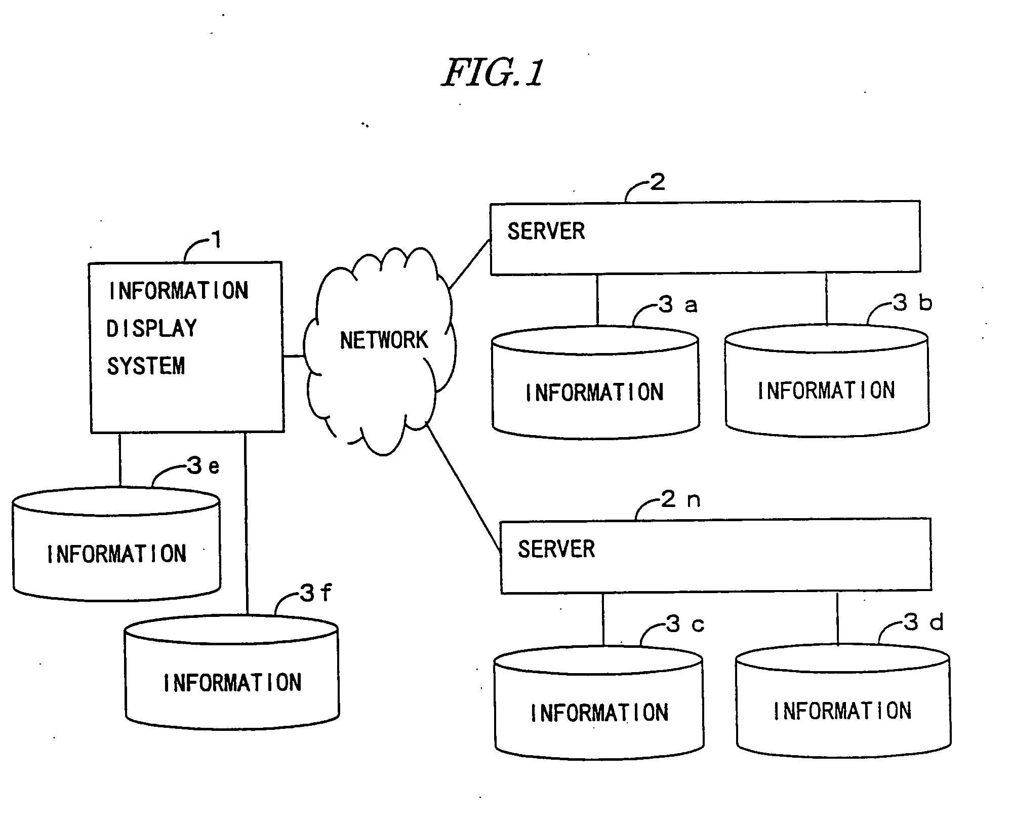
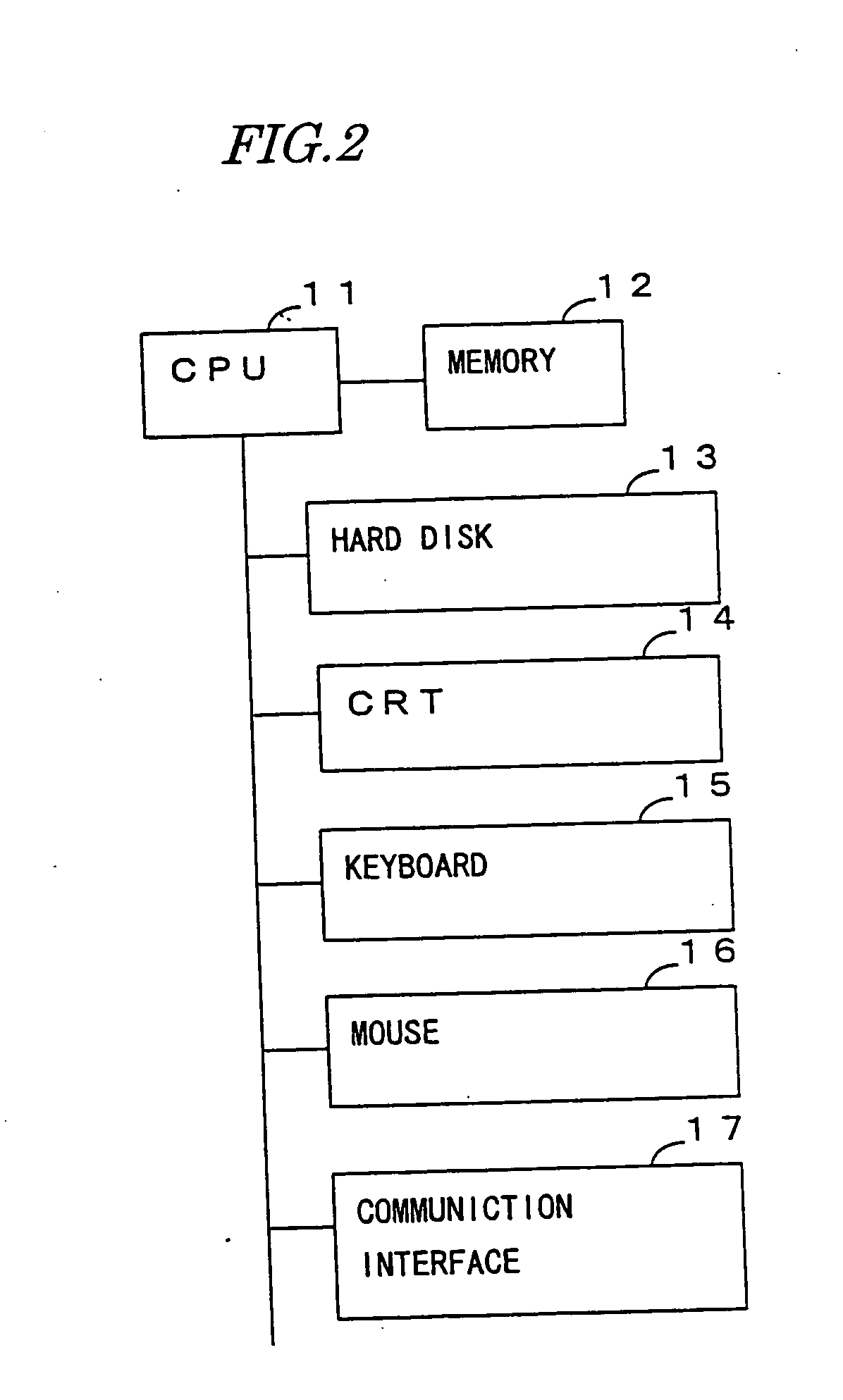
[0070]FIG. 1 is a view showing an architecture of a network to which the information display system 1 in the first embodiment has an access. FIG. 2 is a view illustrating a hardware architecture of the information display system 1. FIG. 3 is a diagram showing a data structure of a channel table used by the information display system 1. FIG. 4 is a view showing an example of display on a single screen in the information display system 1. FIG. 5 is a view showing a 2-divided screen. FIG. 6 is a view showing a 4-divided screen. FIG. 7 is a view showing a 9-divided screen. FIG. 8 is a diagram showing a data structure of a history management table used by the information display system 1. FIG. 9 is a flowchart showing a process of a browser (a program for browsing the information) executed by a CPU 1 of the information display system 1. FIGS. 10 and 11 are flowcharts e...

second embodiment

[0173]FIGS. 16 and 17 show processes by the information display system 1 in a second embodiment of the present invention.

[0174]FIG. 16 is an explanatory diagram showing operations effected on the dial object 20 displayed on the CRT 14 of the information display system 1 in accordance with the second embodiment. FIG. 17 is a flowchart showing a process of detecting the operation effected on this dial object 20.

[0175] The first embodiment has exemplified the information display system 1 constructed such that the channel table is stored with the plurality of URLs, and the information displayed in one or the plurality of display areas. The channel is switched over by clicking one of the numerals or the character string representing one of the 2- through 9-divisions in the dial object 20.

[0176] There will be explained the information display system 1 in the second embodiment, wherein the indicator 21 in the dial object 20 is turned by manipulating left and right buttons of the mouse 1...

modified example

[0193] In the embodiment discussed above, the dial object 20 is, as shown in FIG. 16, constructed of the numerals and the character strings (the dial characters) representing the number of divisions, which are arranged along the circumference, and the indicator 21 turning about the center of the circumference. The embodiment of the present invention is not, however, limited to the configuration itself of the dial object 20 described above. For example, the dial object 20 may also take such a configuration that the object 20 does not include the indicator 21, and an indicated position is shown by reversing the numeral or the character string representing the number of divisions in a black-and-white mode. The indicator 21 may be formed in an annular shape or may include a projection for indicating a predetermined position.


PUM


Abstract

Disclosed is an information display system capable of efficiently browsing items of information related by links. When displaying the information obtained by accessing a network, a plurality of display areas are formed, and plural items of information are displayed in these display areas. In this case, a display history of the information displayed may be stored, and the items of information displayed at the present or in the past may be displayed in a predetermined order in the respective display areas. When a first item of information displayed in a first display area is related to a second item of information, and when given an indication of displaying a second item of information, the second item of information may be displayed in a second display area while keeping the display of the first item of information in the first display area.

Description

CROSS-REFERENCE TO RELATED APPLICATIONS [0001] This application is a continuation of application Ser. No. 09 / 764,302, filed Jan. 19, 2001, and now allowed, which further claims the benefit of priority Japanese Patent Application No. 2000-135030, filed May 8, 2000, the contents of which are incorporated herein by reference.BACKGROUND OF THE INVENTION [0002] The present invention relates to an information display system having a graphical user interface (GUI). [0003] With a spread of the Internet over the recent years, a technology of readily browsing the information has been demanded. As a result, an information display system incorporating a program known as a browser was developed. The conventional browser has only one display area, and hence the user switches over a page by updating the information in that display area by overwriting, or starting another browser and displaying the information thereon, or rewriting a content in the same display area by selecting an index called a t...

Claims


Application Information

Patent Timeline
IPC IPC(8): G06F17/00G06F3/0484G06F17/30
CPCG06F3/04847G06F17/30899G09G2370/027G06F16/957
Inventor TSUCHIMURA, TADAOTOMARU, TAKESHI
Owner FUJITSU LTD
Learn More