Methods and systems for detecting dryness of clothes in an appliance

a technology of clothes and dryness, applied in the field of clothes treatment apparatus, can solve problems such as unsatisfactory dryness

Active Publication Date: 2007-05-31
HAIER US APPLIANCE SOLUTIONS INC
View PDF17 Cites 12 Cited by
  • Summary
  • Abstract
  • Description
  • Claims
  • Application Information

AI Technical Summary

Benefits of technology

[0005] In one aspect, a control system for a fabric care apparatus is provided. The apparatus includes a cabinet, a wash tub mounted within the cabinet and configured to receive clothes therein, a dehumidifying assembly, and a fan configured to draw air from the wash tub to the dehumidifying assembly and channel the air from the dehumidifying assembly back to the wash tub. The control system includes a f

Problems solved by technology

However, the appropriate time period is varied based on the types of chemical that is used to wash or rinse the clothes, and a drying time

Method used


Image

  • Methods and systems for detecting dryness of clothes in an appliance
  • Methods and systems for detecting dryness of clothes in an appliance
  • Methods and systems for detecting dryness of clothes in an appliance

Examples


Embodiment Construction

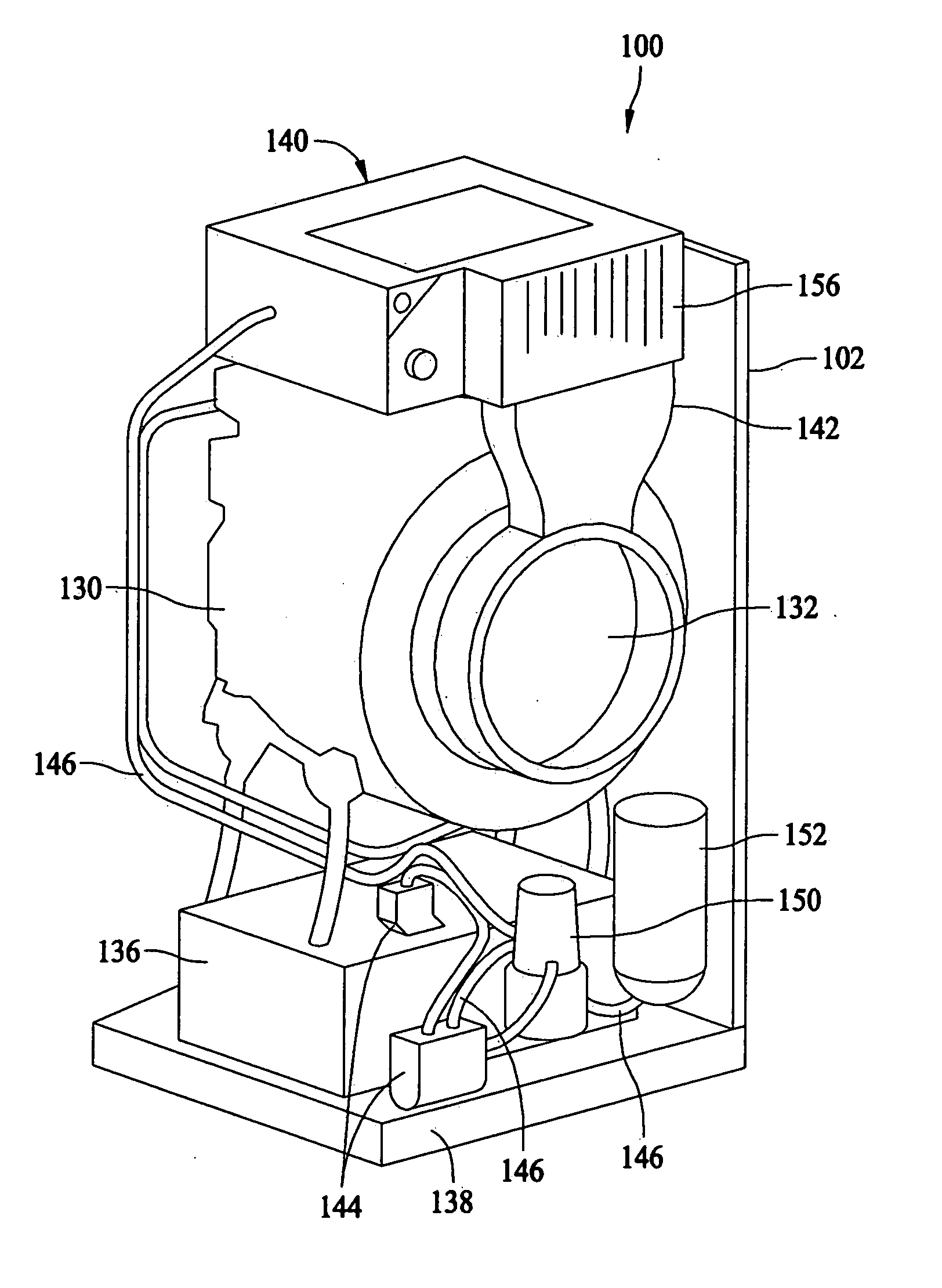
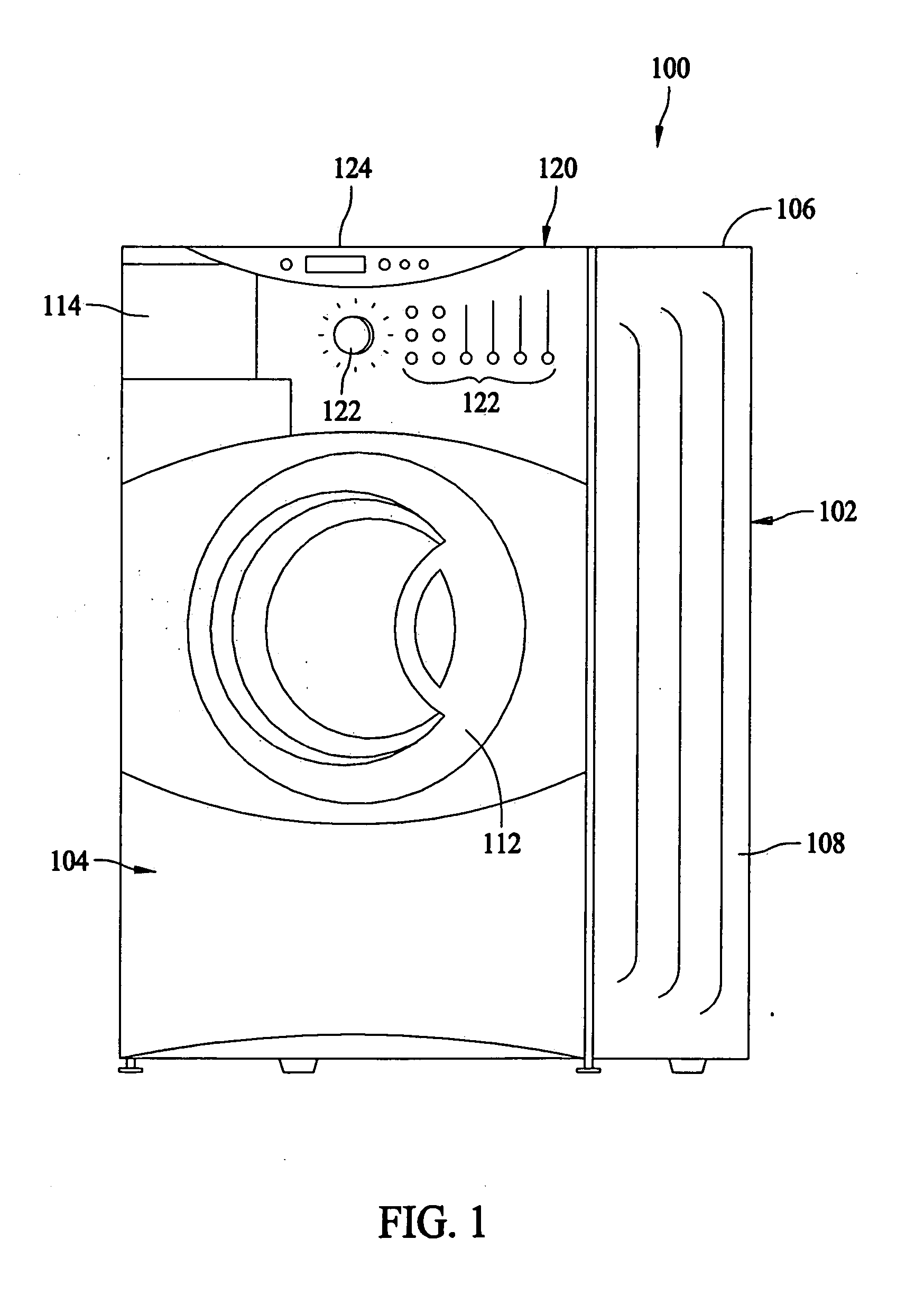
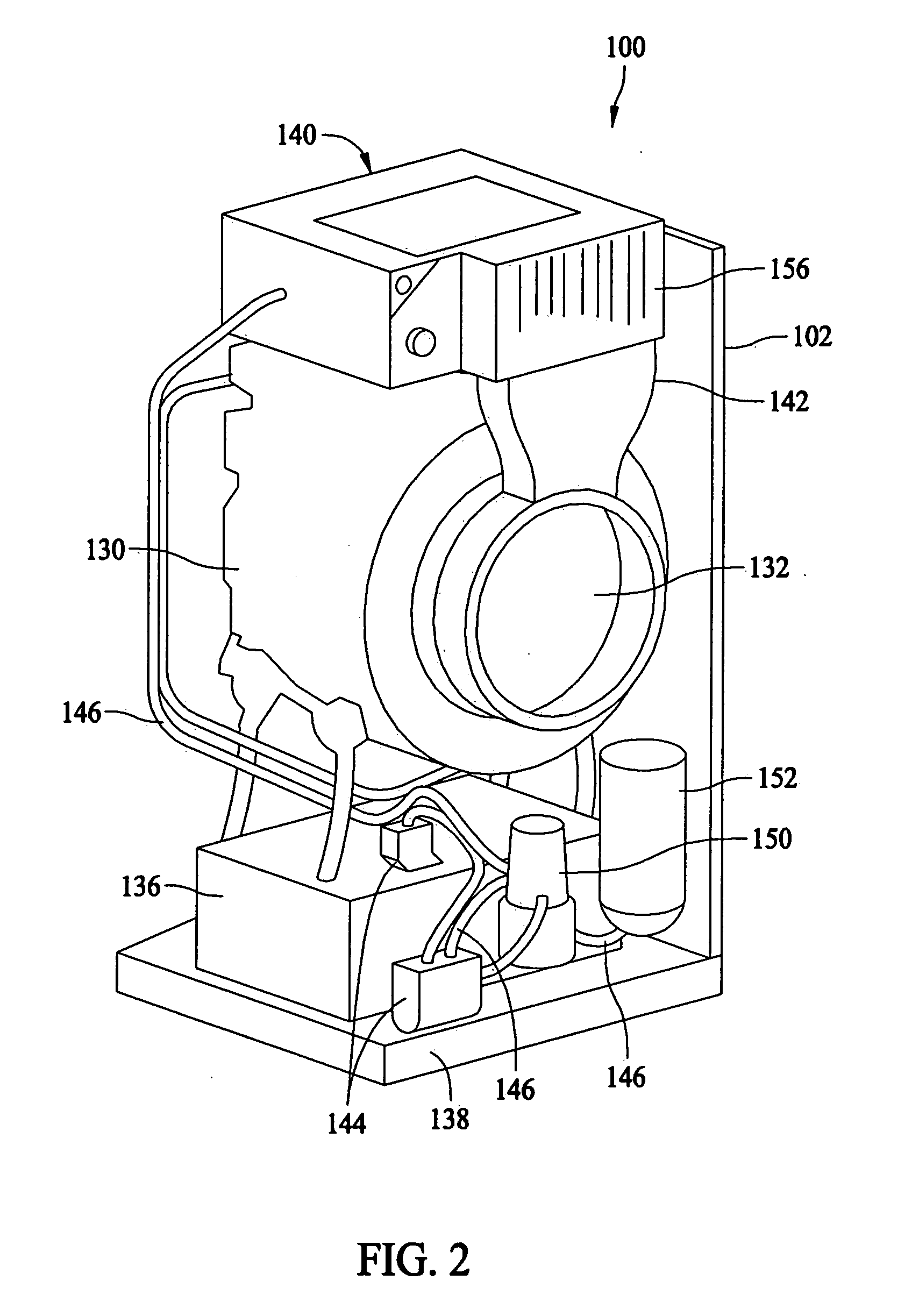
[0014]FIG. 1 is a perspective view of an exemplary fabric care machine 100. Fabric care machine 100 includes a cabinet 102 having a front panel 104, a top panel 106, and side panels 108. A door 112 is mounted to front panel 104 and is rotatable about a hinge (not shown) between an open position (not shown) facilitating access to a basket (not shown) in the interior of machine 100 that holds a clothes load, and a closed position (as shown in FIG. 1) forming a substantially sealed enclosure over the basket. Front panel 104 also includes a cover 114 that covers a dual lint filter user interface (see FIG. 2). A control panel 120 including a plurality of input selectors 122 is coupled to an upper portion of front panel 104. Control panel 120 and input selectors 122 collectively form a user interface for operator selection of machine cycles and features, and, in one embodiment, a display section 124 indicates selected features, machine status, and other items of interest to users.

[0015] ...


PUM


Abstract

A control system for a clothes treating apparatus includes a first temperature sensor, a second temperature sensor, and a controller operatively coupled to the sensors. The apparatus includes a cabinet, a wash tub mounted within the cabinet and configured to receive clothes therein, a dehumidifying assembly, and a fan configured to draw air from the wash tub to the dehumidifying assembly and channel the air from the dehumidifying assembly back to the wash tub. The first temperature sensor is configured to detect a temperature of the air entering the dehumidifying assembly. The second sensor is configured to detect a temperature of the air exiting the dehumidifying assembly. The controller is configured to determine a dryness level of the clothes contained in the wash tub based on the detected air temperatures.

Description

BACKGROUND OF THE INVENTION [0001] This invention relates generally to clothes treating apparatus, and, more particularly, to methods and systems for detecting dryness of clothes in an apparatus. [0002] At least some known fabric care machines include a cabinet that houses an outer tub for containing a quantity of cleaning fluid, a perforated clothes basket within the tub, and a storage tank for storing the cleaning fluid. A drive and motor assembly is mounted underneath the stationary outer tub to rotate the basket within the tub. Generally, the cleaning machine performs a cleaning cycle followed by a spin cycle and a drying cycle. [0003] In at least one cleaning cycle, the clothes are saturated with cleaning fluid and tumbled in an amount of cleaning fluid. The cleaning fluid dissolves certain fluid soluble soils. The clothes are tumbled to dislodge some insoluble soils and generally to increase the effectiveness of the cleaning process. Due to the cost of certain cleaning fluids,...

Claims


Application Information

Patent Timeline
IPC IPC(8): D06F33/00D06F35/00D06F34/18D06F58/38
CPCD06F58/28D06F2058/2829D06F58/38D06F2103/08D06F34/18D06F2101/16D06F2105/62D06F2103/30D06F2103/32D06F2105/30
Inventor MILLS, ROBERTWORTHINGTON, TIMOTHY
Owner HAIER US APPLIANCE SOLUTIONS INC
Why Eureka
Try Eureka