Airless spare tire

a spare tire and airless technology, applied in the field of tires, can solve the problems of not being able to carry a significant load at high speeds, not being able to carry a load, solid tires, etc., and achieve the effects of running cooler and even greater loads, less weight, and simple structur

Inactive Publication Date: 2007-05-31
AMERITIRE
View PDF22 Cites 50 Cited by
  • Summary
  • Abstract
  • Description
  • Claims
  • Application Information

AI Technical Summary

Benefits of technology

[0009] Still another object of the present invention is to provide a spare tire formed from an elastomeric material to have less weight than earlier elastomeric tires of comparable in size, will support a load that is comparable to or greater than a load supported by such earlier elastomeric tires and will run cooler and even greater loads and longer distances than will such earlier elastomeric tires.
[0010] Still another object of the present invention is to provide a is an elastomeric tire that is simple to form by molding or casting methods in a single operation and will provide a unique tire design with equal spaced cavities formed in both side walls, providing a tire that is of lesser weight than a comparable size of a solid elastomeric tire and will run longer and support a greater load at greater speeds than such comparable size of solid elastomeric tire.
[0011] The present invention is in an airless spare tire formed from an elastomeric material, preferably a polyurethane material, by molding or casting methods. The tire includes a top or outer tread area, has an open center area arranged for mounting onto a wheel, or may be cast onto a wheel during its formation. Center sections around both the tire side walls include a plurality of like equally spaced apart cavities, formed as parallelograms with rounded comers. The cavities are equidistant from the tire center and each is spaced apart an equal distance from adjacent cavities, leaving wall sections between the parallelogram longest sides. Which cavities are of a uniform depth and extend to, and are spaced apart by, a tire center dividing wall. The set of cavities around one tire side are slightly offset from the cavities on the other side wall, and are separated by the tire center diving wall, whereby the wall sections of a cavity on the one side will align with to appear to cross the opposite wall section. So arranged, the off set side wall sections are connected by the center dividing wall and tend to function as trusses, providing, depending upon slope of the parallelogram longest side to a radial across the tire side wall, an X truss to a V truss, for transferring compressive loads exerted through the tire tread, across the tire wall sections and into the tire mounting to a wheel. A load bearing capability is thereby provided to the tire of the invention that is at least as strong as is provided by a like size of a solid elastomeric tire and at a significantly lesser tire weight. Which cavities and adjacent side walls sections will also provide flexure to the tire during travel under load, to essentially mimic the ride provided by a pneumatic tire.

Problems solved by technology

Such solid tires, of course, were not capable of carrying a significant load at high speeds, or for carrying a load at highway speeds.
In addition to which run flat tires, some companies have produced solid elastomeric tires manufactured onto or mounted to a wheel, that will provide limited service in the event of a tire deflation.

Method used


Image

  • Airless spare tire
  • Airless spare tire
  • Airless spare tire

Examples


Embodiment Construction

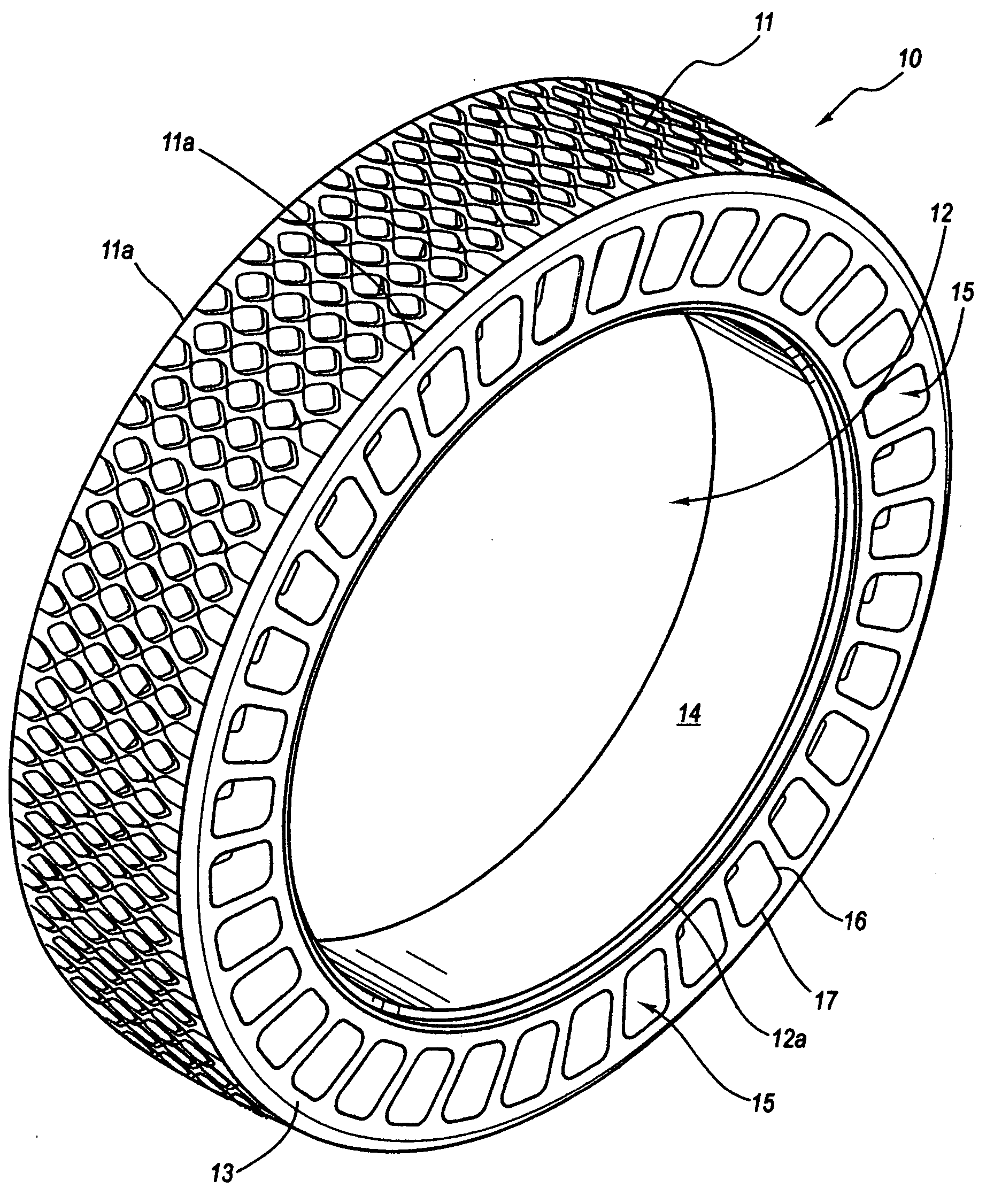
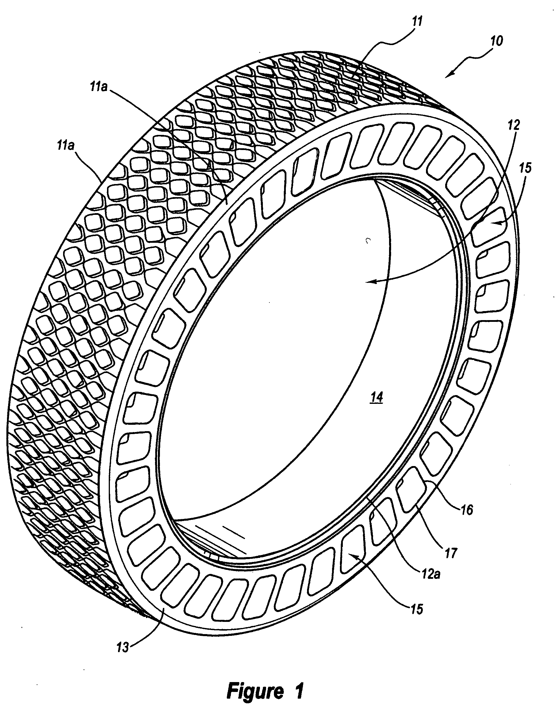
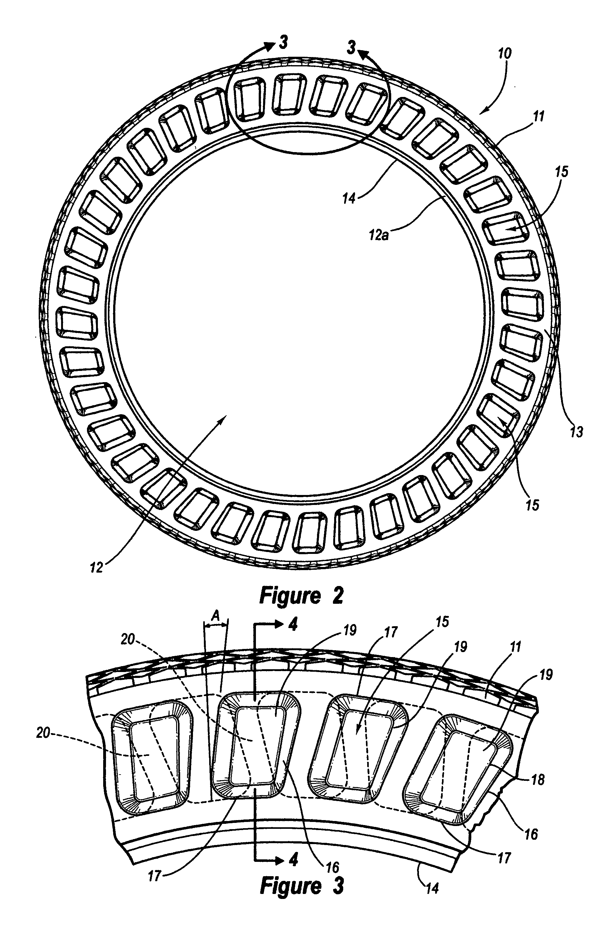
[0019] The invention is in an airless spare tire 10, as shown in FIG. 1, is formed with an outer tread 11 across its top surface, preferably having a traction enhancing surface, shown as a diamond pattern, though, it should be understood, any traction enhancing pattern could be employed, within the scope of this disclosure. The tire 10 is open at its center 12 to fit onto a wheel, not shown, and includes like side walls 13. The side walls 13 extend downwardly from both tread edges 11a, that are shown as being beveled, and terminate at wheel steps 12a. The steps 12a to step towards the tire center to a wheel rim mounting surface 14, that is flat thereacross. Unique to the invention, as shown best in FIG. 4, the tire side walls 13 include spaced cavities 15, formed into the side walls, that are at equal spaced intervals therearound, leaving a tire wall section 20 between adjacent cavities. The tire 10 is preferably formed by molding or casting methods from a mixture of urethane consti...


PUM

PropertyMeasurementUnit
angleaaaaaaaaaa
diameteraaaaaaaaaa
high speed testingaaaaaaaaaa

Abstract

An airless spare tire formed from an elastomeric material, preferably a polyurethane material, that includes an outer tread, like side walls and a closed undersurface, and where the side walls have identical spaced cavities formed therein, each to intersect a center section, and which cavities each have the shape of a parallelogram with rounded corners, and have one long side at a selected angle to a tire radius from the tire center, with their short sides essentially parallel to the tire tread. Which cavities on one side of the tire are offset to those on the other tire side and the angle of the parallelogram shaped cavity long side to a radial is selected to provide for an alignment of side wall sections on one tire side with end or centers of the side wall sections on the other tire side.

Description

BACKGROUND OF INVENTION [0001] 1. Field of The Invention [0002] This invention pertains to tires formed from an elastomeric material by spin casting, vacuum forming, or other casting process, providing a solid tire suitable for limited use as a vehicle spare tire. [0003] 2. Prior Art [0004] The present invention is in an airless spare tire that is formed from an elastomeric material, preferably a polyurethane. The tire, formed from a urethane material, is for mounting to a rim, and the tire and rim wheel combination are maintained within or without a vehicle until needed as when one of the vehicle's pneumatic tires deflates. Very early tires and spare tires were formed as solid rings from an elastomeric material and some examples of such are shown in earlier U.S. patents to Divine, U.S. Pat. No. 1,056,975; to Henderson, U.S. Pat. No. 1,194,177; and to Hitchner, U.S. Pat. No. 1,670,721, that illustrate very early uses of solid elastomeric tires on buggies and early automobiles. Such ...

Claims


Application Information

Patent Timeline
Patent Type & Authority Applications(United States)
IPC IPC(8): B60C7/00
CPCB60C7/10B60C7/12B60C17/06B60C2007/005B60C17/061
Inventor STEINKE, RICHARD A.LOVE, THEODORE M.MOORE, JAMES G.
Owner AMERITIRE
Why Eureka
Try Eureka