Methods and apparatus for determining reverse path delay

a reverse path delay and delay technology, applied in the field of network communication, can solve the problems of significant limitations of using rtt as a congestion metri

Inactive Publication Date: 2007-05-31
CISCO TECH INC
View PDF18 Cites 64 Cited by
  • Summary
  • Abstract
  • Description
  • Claims
  • Application Information

AI Technical Summary

Problems solved by technology

However, using RTT as a metric for determining congestion has significant limitations.

Method used


Image

  • Methods and apparatus for determining reverse path delay
  • Methods and apparatus for determining reverse path delay
  • Methods and apparatus for determining reverse path delay

Examples


Embodiment Construction

[0020] Reference will now be made in detail to some specific embodiments of the invention including the best modes contemplated by the inventors for carrying out the invention. Examples of these specific embodiments are illustrated in the accompanying drawings. While the invention is described in conjunction with these specific embodiments, it will be understood that it is not intended to limit the invention to the described embodiments. On the contrary, it is intended to cover alternatives, modifications, and equivalents as may be included within the spirit and scope of the invention as defined by the appended claims.

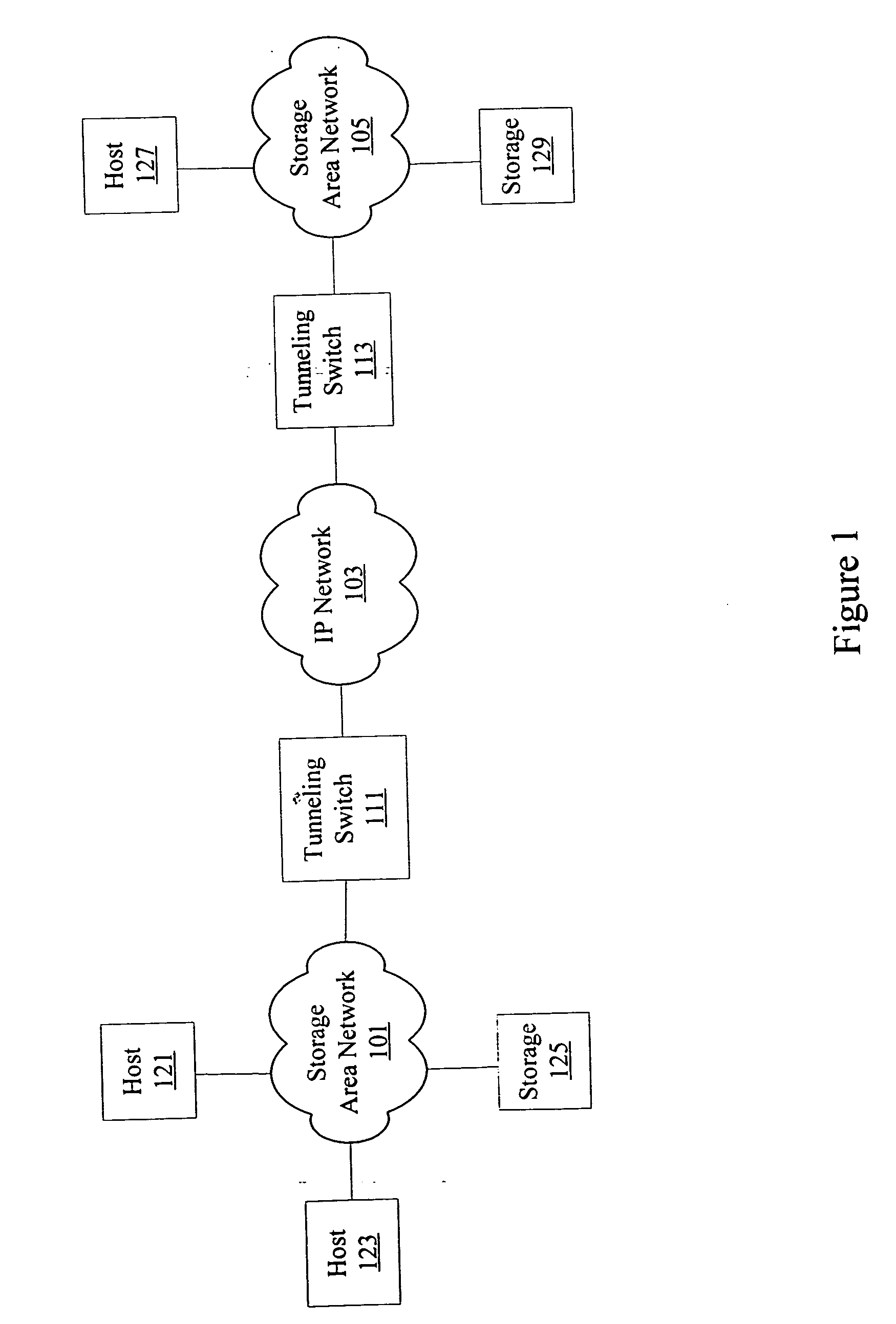
[0021] For example, the techniques of the present invention will be described in the context of the transmission control protocol (TCP) stack implemented in an intelligent fibre channel switch. However, it should be noted that the techniques of the present invention can be applied to different variations and flavors of TCP as well as to alternatives to TCP. In the fol...


PUM


Abstract

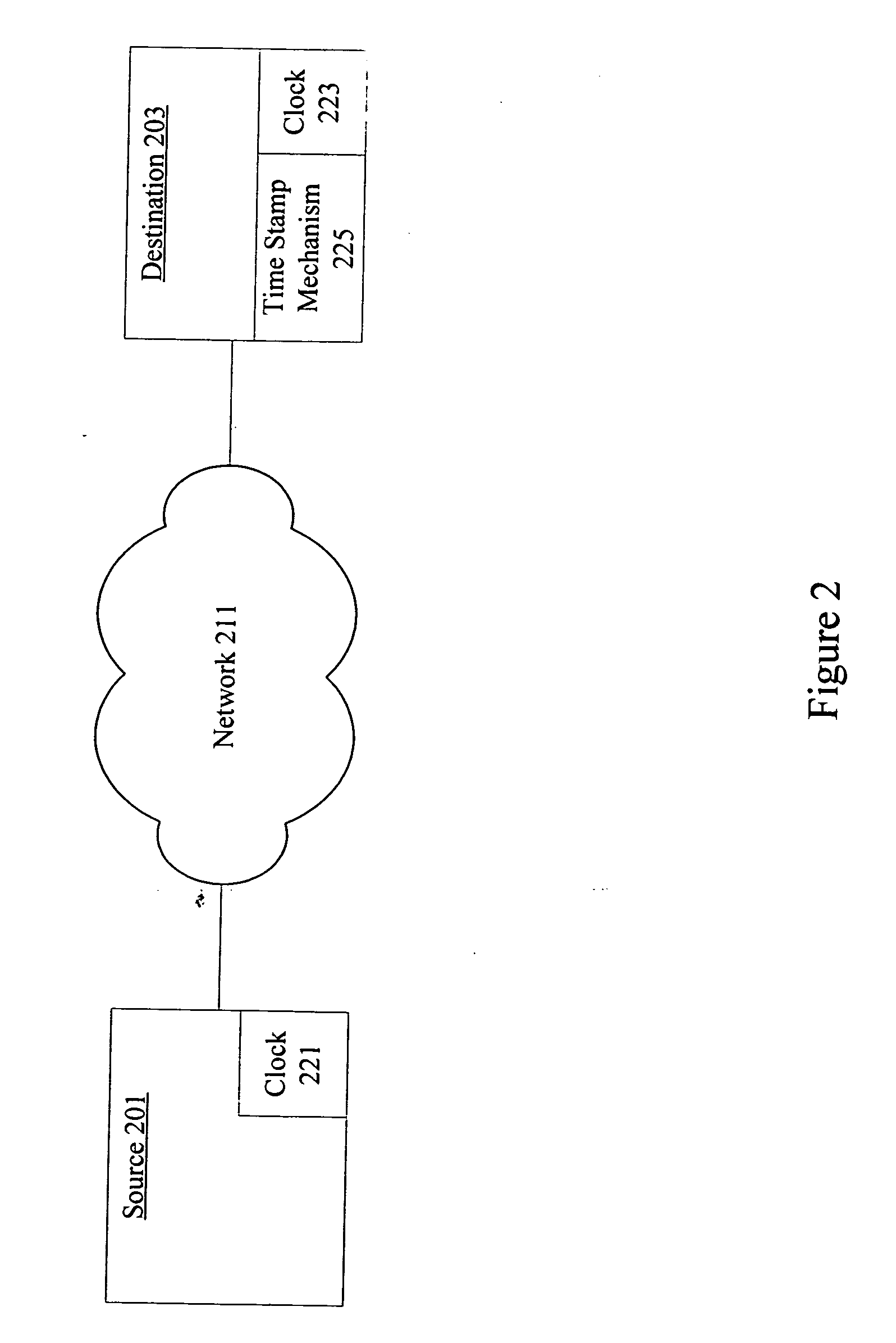
According to the present invention, methods and apparatus are provided for determining components of a round trip time (RTT). A source node sends data to a destination node. The destination node inserts a timestamp into an acknowledgment and sends the acknowledgment back to the source node. The source node determines the RTT from its own measurements and estimates reverse path delay by comparing timestamps to expected timestamps. Considerations for destination node timestamp speed differences are provided.

Description

CROSS REFERENCE TO RELATED CASES [0001] The present application is related to concurrently filed U.S. patent application No. _ / ______, titled TRANSMISSION CONTROL PROTOCOL (TCP) CONGESTION CONTROL (Atty Docket No. CISCP460) by Guglielmo M. Morandin, the entirety of which is incorporated by reference for all purposes.BACKGROUND OF THE INVENTION [0002] 1. Field of the Invention. [0003] The present invention generally relates to networking. More specifically, the present invention provides techniques and mechanisms for determining reverse path delay associated with a round trip time measurement. [0004] 2. Description of Related Art [0005] Round trip time (RTT) is a commonly used networking metric for determining congestion between a source and a destination in a variety of networks. Networking tools and utilities allow a source to send data to a destination and the destination to respond to the source. The measured time between transmission of the data and receipt of the acknowledgment...

Claims


Application Information

Patent Timeline
Patent Type & Authority Applications(United States)
IPC IPC(8): H04J1/16
CPCH04J3/0682
Inventor MORANDIN, GUGLIELMO M.
Owner CISCO TECH INC
Why Eureka
Try Eureka