
Clock synchronization for a machine control system

Active Publication Date: 2007-05-31
CATERPILLAR INC
View PDF7 Cites 7 Cited by
  • Summary
  • Abstract
  • Description
  • Claims
  • Application Information

AI Technical Summary

Benefits of technology

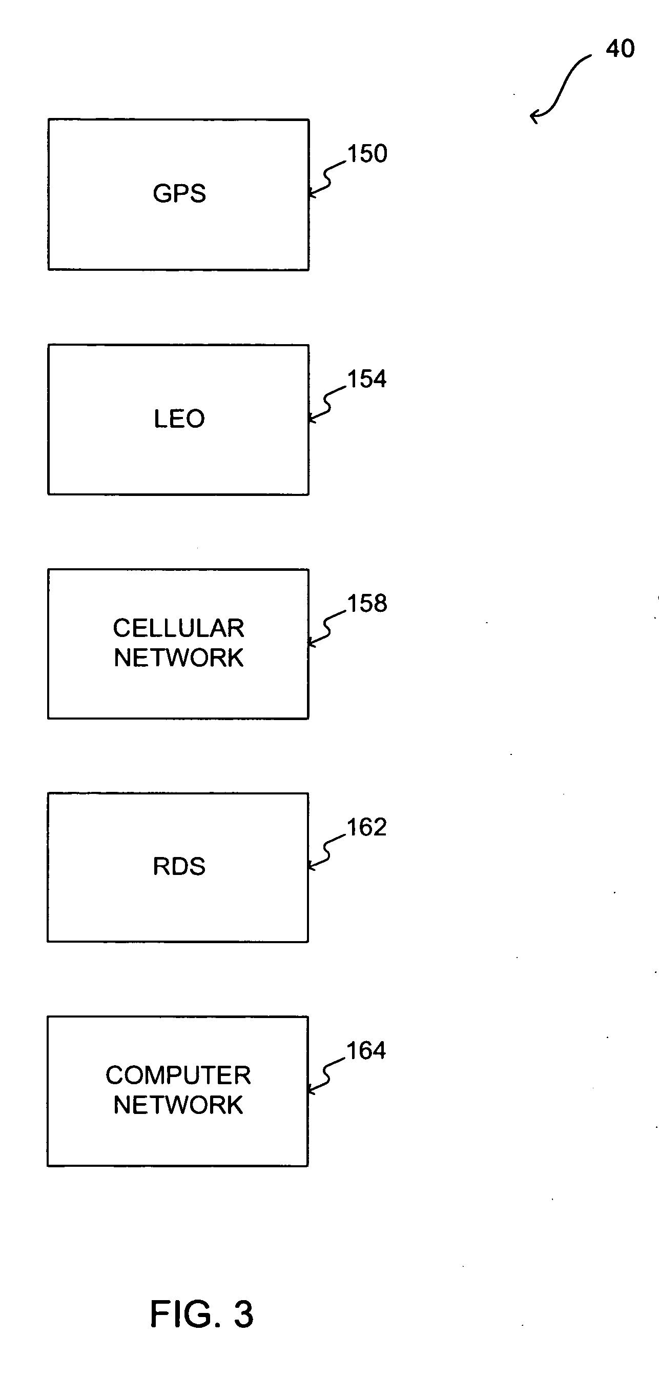
[0008] One aspect of the present disclosure includes a clock synchronized control system. The system may include a controller configured to control at least one function of a work machine. The controller may also be configured to select a clock source from among a plurality of external clock sources based on a predetermined order. The controller may be further configured to obtain information from the selected clock source. The controller may also be configured to use the obtained information to affect the at least one function of the work machine.
[0009] Another aspect of the present disclosure includes a method for clock synchronized control of a machine. The method may include selecting a clock source from among a plurality of external clock sources based on a predetermined order. The method may also include obtaining information from the selected clock source. The method may also include using the obtained information to affect at least one function of a work machine.
[0010] Yet another aspect of the disclosure includes a clock information transfer system. The system may include a first work machine including a controller configured to control at least one function of the first work machine. The controller may also be configured to select a clock source from among a plurality of external clock sources based on a predetermined order. The controller may be further configured to obtain clock informatio

Problems solved by technology

However, there may be problems associated with obtaining clock information from an on-board battery-operated clock.
Specifically, the battery-operated clock may not provide accurate clock information.
This lack of accuracy may be due to the climatic conditions in which the machine operates.
A large temperature gradient may cause the battery-operated clock to lose its accuracy over a period of time.
Therefore, as time goes by, some functions performed by the machine may be affected by this lack of clock accuracy.
For example, messages sent by a machine including time stamps generated by an on-board battery-operated clock may not include accurate clock information.
This lack of clock accuracy may lead to problems in many instances, especially where other entities, such as, for example, other machines, or an off-board control system, may rely on time-sensitive information sent by the machine.
This may be problematic because not every controller in a network may have the capability to connect to an external clock source.
Furthermore, the '926 patent does not disclose the use of more than one external clock source.
This may be problematic if the only external clock source being used becomes unavailable.

Method used


Image

  • Clock synchronization for a machine control system
  • Clock synchronization for a machine control system
  • Clock synchronization for a machine control system

Examples


Embodiment Construction

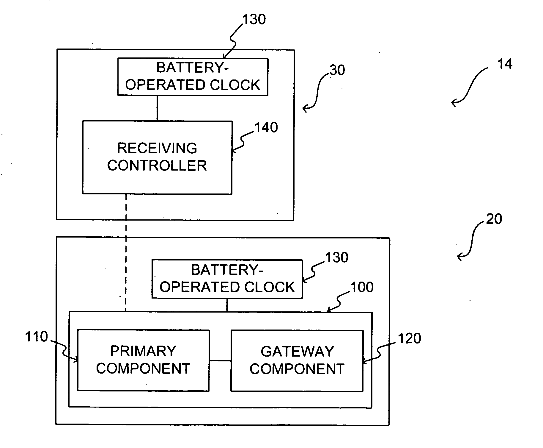
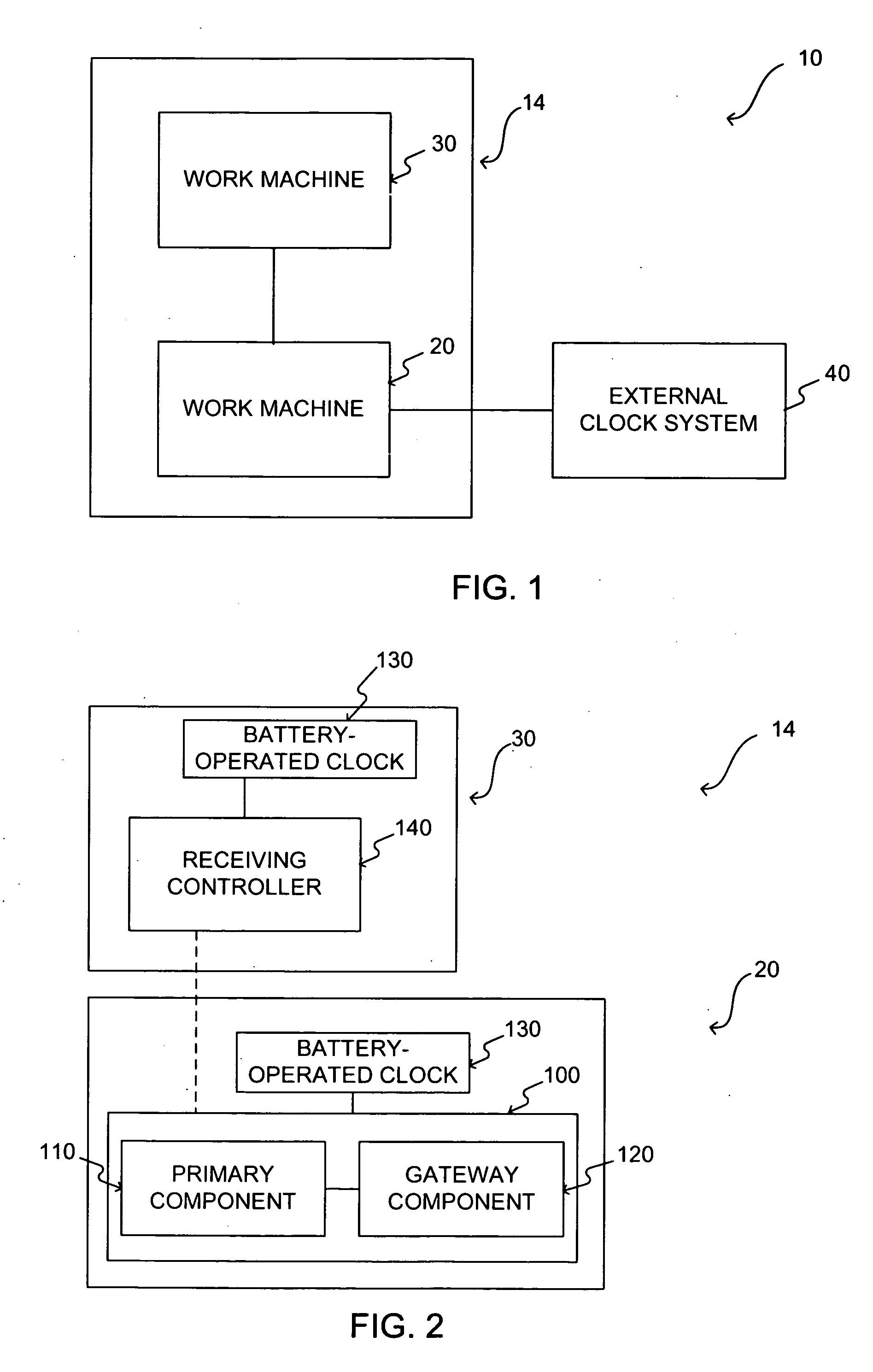
[0016]FIG. 1 provides a block diagram representation of a clock synchronized control system 10. System 10 includes a work machine system 14 that may include work machines 20 and 30. System 10 also includes external clock system 40. Work machine 20 and work machine 30 may include a track type tractor, a truck, wheeled tractor, dump truck, automobile, on-highway vehicle, off-highway vehicle, skid-steer, stationary generator, air compressor, or any other such machine. External clock system 40 may be physically separate from work machines 20 and 30, and may include a plurality of clock sources configurable to provide information to work machine 20. One skilled in the art will appreciate that while only two work machines are shown as part of work machine system 14, any number of work machines may be included in work machine system 14.

[0017] Work machines 20 and 30 may include a power source (not shown) and a frame (not shown). The power source may include one or more devices configured ...


PUM


Abstract

A clock synchronized control system includes a controller configured to control at least one function of a work machine. The controller may also be configured to select a clock source from among a plurality of external clock sources based on a predetermined order. The controller may be further configured to obtain information from the selected clock source. The controller may also be configured to use the obtained information to affect the at least one function of the work machine.

Description

TECHNICAL FIELD [0001] The present disclosure is related to a system and method for obtaining information from an off-board clock source and, more particularly, to a system and method for receiving information from a plurality of off-board clock sources and synchronizing work machines using the received information. BACKGROUND [0002] Many machines include on-board systems such as electronics, software, etc., that perform certain functions that make use of clock information. These functions may include, for example, logging and reporting the occurrence of events at specific times, automatically performing certain tasks at predetermined times, etc. Furthermore, a number of machines that are geographically dispersed, but yet part of the same fleet, may exchange information with each other by sending messages directly to each other. These messages may include timestamps indicating, for example, the time a message was sent from a work machine, the time a particular task was performed by ...

Claims


Application Information

Patent Timeline
IPC IPC(8): G06F15/16
CPCH04J3/0638H04J3/0655H04J3/0661G05B19/414G05B2219/33097G05B2219/33144
Inventor MCNEALY, ANTHONY D.FERGUSON, ALAN L.
Owner CATERPILLAR INC
Learn More