
Method of locating printhead on printer

Inactive Publication Date: 2007-06-07
MEMJET TECH LTD +1
View PDF7 Cites 26 Cited by
  • Summary
  • Abstract
  • Description
  • Claims
  • Application Information

AI Technical Summary

Benefits of technology

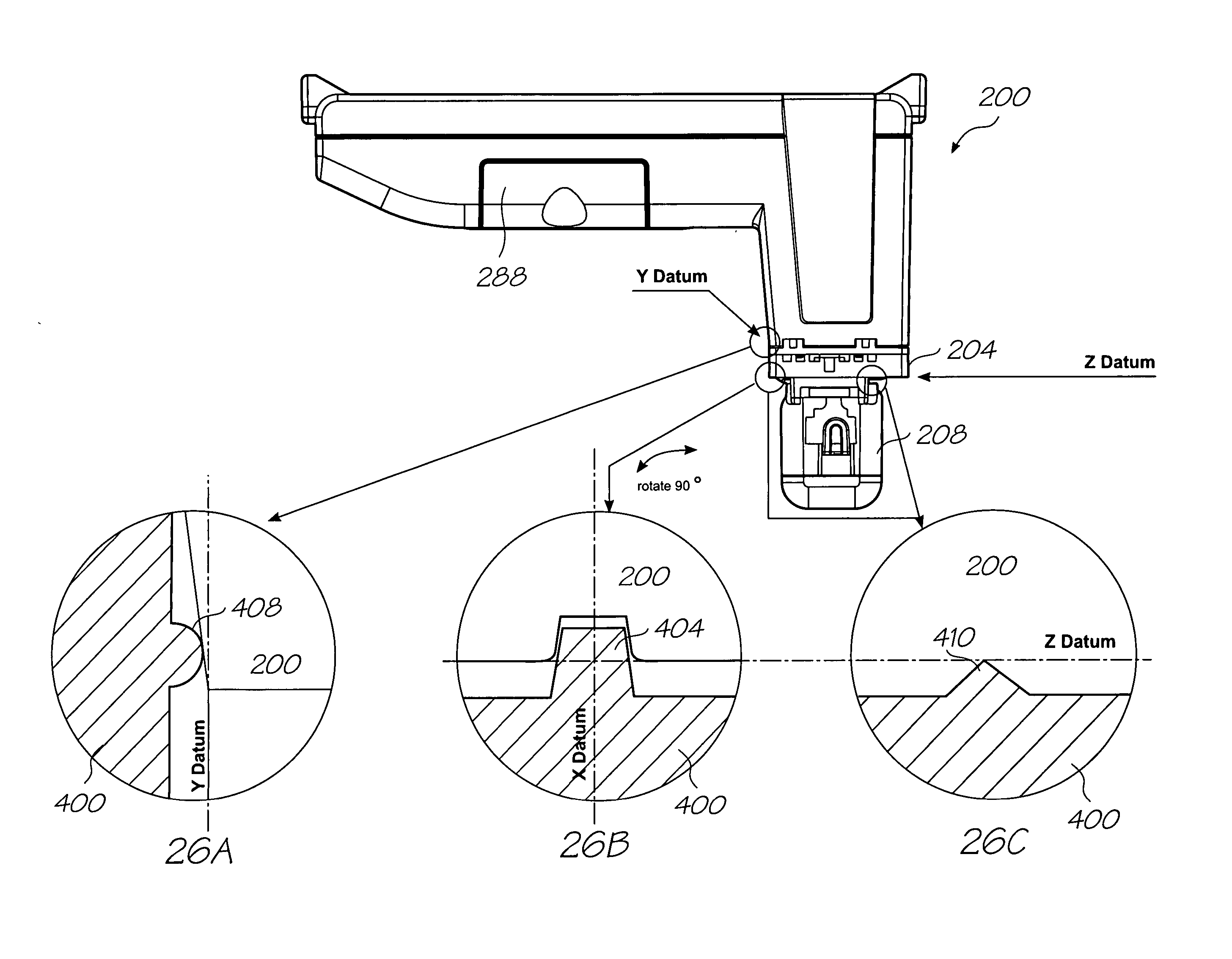
[0005] The present invention provides the reference features directly on the assembly mounting the printhead ICs, thereby eliminating the effect of misalignment and movement of the printhead IC assembly with respect to the printing cartridge on determining the location of the nozzles. The assembly of the cartridge is also simplified, and substantially a full printing range across the 100 mm page width for 4 inch by 6 inch digital photo printing is provided, due to the low tolerance provided by the arrangement.
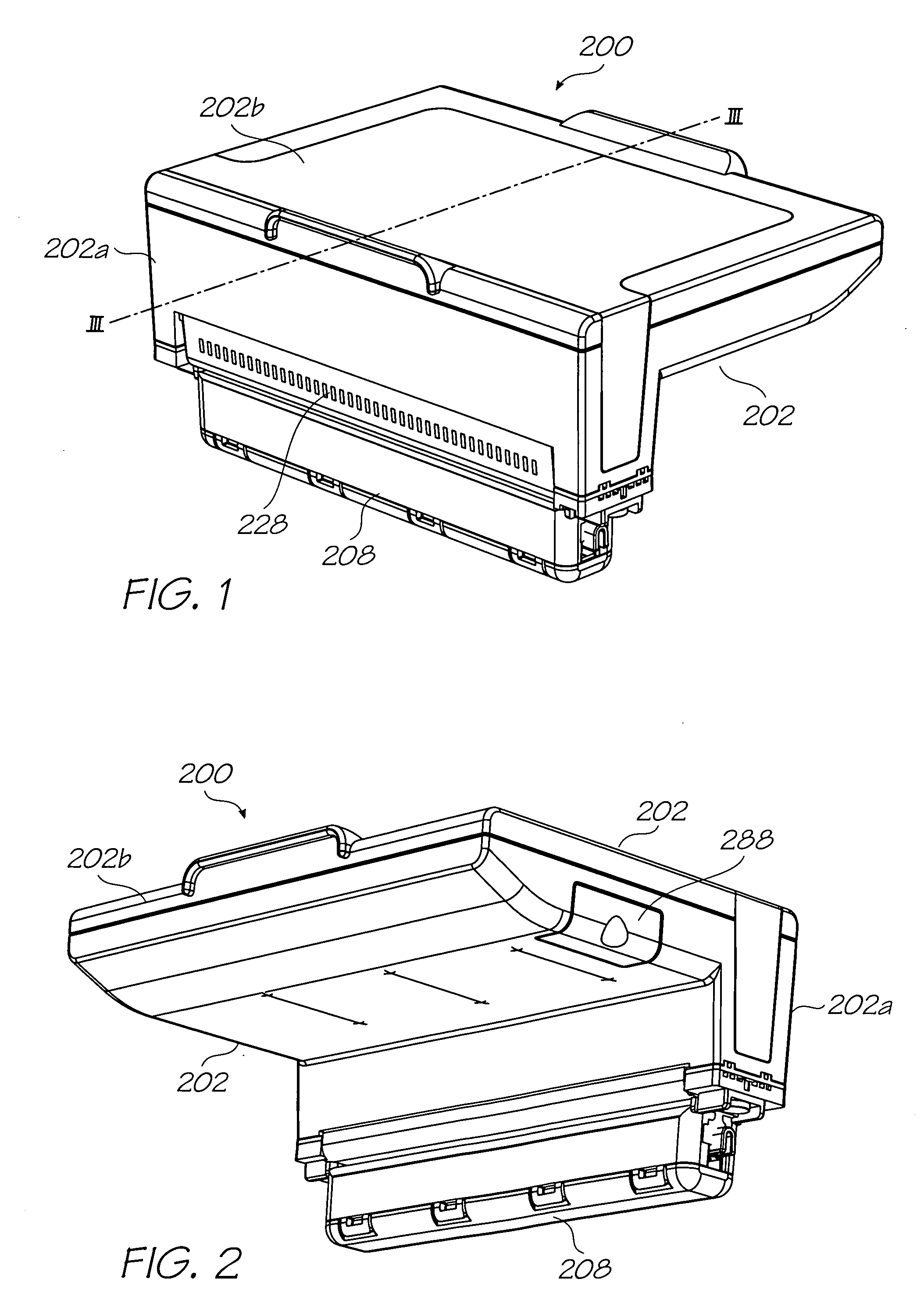
[0099] Optionally, the confining arrangement incorporates aligned slots through each of the cartridge body, printhead assembly and capping mechanism, a second pin configured to pass through each of the slots and a biasing member for locking the second pin within the slots and biasing the cartridge body, printhead assembly and capping mechanism together at the second pin whilst allowing relative movement of the cartridge body, printhead assembly and capping mechanism.
[0137] applying inwardly directed force on at least one exterior wall of the ink bag so as to reduce an available fluid volume of the ink bag, thereby causing ink to flow from the ink bag to the nozzles along the fluid path; and
[0138] arranging a biasing member in the ink bag so that the biasing member applies outwardly directed force on at least one interior wall of the ink bag so as to restrain the reduction of available fluid volume of the ink bag only once the available fluid volume of the ink bag has been reduced to a predetermined volume.

Problems solved by technology

However, referencing the nozzles in this way fails to take account of misalignment and movement of the printhead ICs relative to the cartridge body.
In systems requiring low nozzle alignment tolerances, such as color inkjet printers for digital photo printing, such discrepancies can be detrimental to print quality.

Method used


Image

  • Method of locating printhead on printer
  • Method of locating printhead on printer
  • Method of locating printhead on printer

Examples


Embodiment Construction

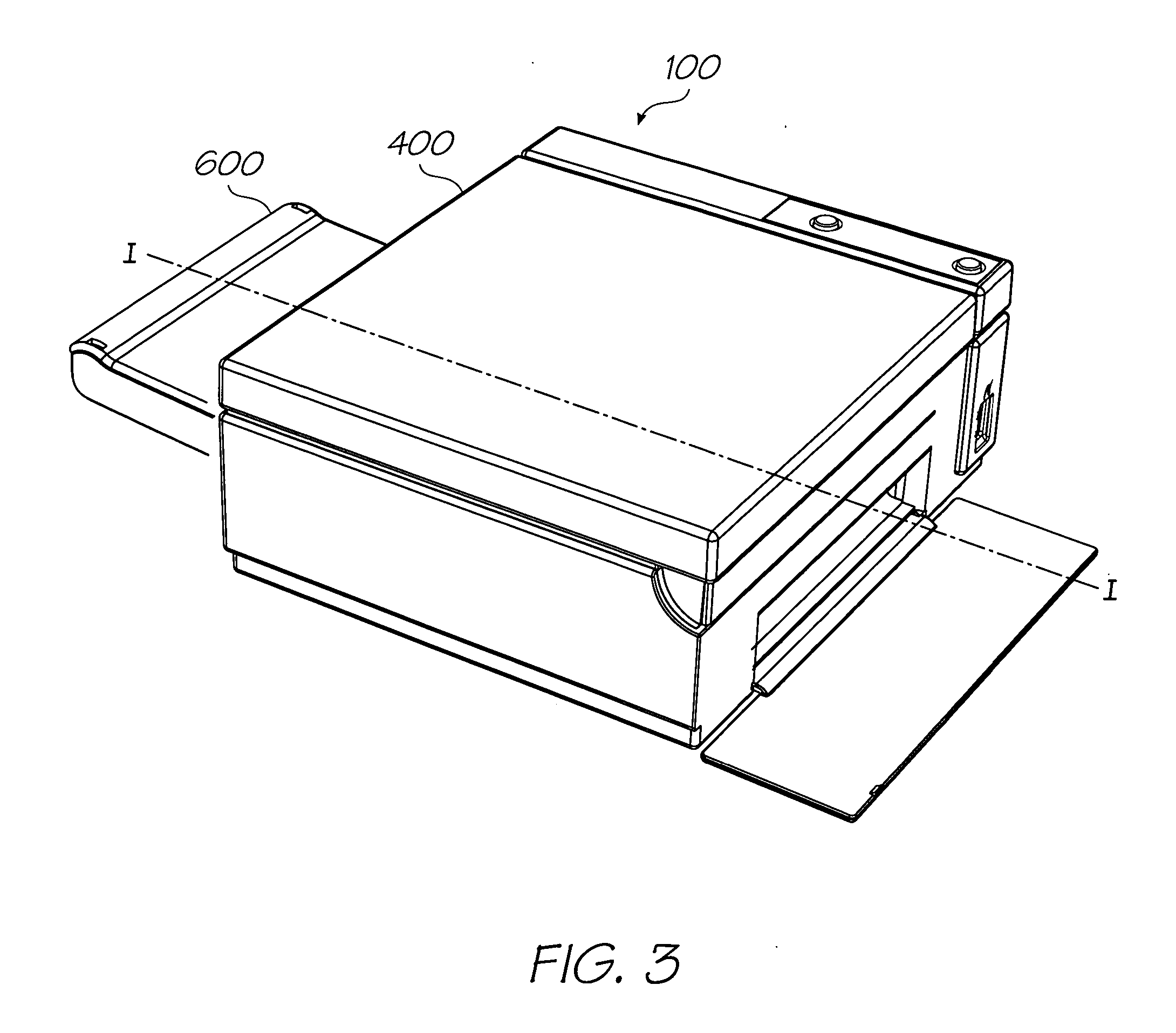
[0229] A printer 100 is provided which is intended for use as a digital photo color printer and is dimensioned to print 100 millimetre by 150 millimetre (4 inch by 6 inch) photos whilst being compact in size and light in weight. As will become apparent from the following detailed description, reconfiguration and dimensioning of the printer could be carried out so as to provide for other printing purposes.

[0230] The printer 100 of the illustrated photo printer embodiment has dimensions of 18.6 cm (W); 7.6 cm (H); 16.3 cm (D), and a weight of less than two Kilograms. The compact and lightweight design of the printer provides portability and ease of use.

[0231] The printer 100 may be easily connected to a PC via USB (such as a USB 1.1 port for USB 2.0 compatible PCs) and to digital cameras and other digital photo equipment, such as electronic photo albums and cellular telephones, via USB or PictBridge. Direct printing is available when using Pictbridge compatible digital photo equipme...


PUM


Abstract

A method of locating a printhead assembly on a printer, the method comprising the steps of: providing a printhead assembly comprising at least one printhead integrated circuit having a plurality of ink ejection nozzles and an ink distribution support mounting the, or each, printhead integrated circuit, the ink distribution support being arranged, in use, to distribute ink from the ink supply to the nozzles; mounting the printhead assembly to the printer by bringing at least one reference feature provided on the ink distribution support into cooperation with a corresponding complementary feature of the printer; and determining from the cooperation the location of the nozzles.

Description

CROSS REFERENCES TO RELATED APPLICATIONS [0001] Various methods, systems and apparatus relating to the present invention are disclosed in the following U.S. patents / patent applications filed by the applicant or assignee of the present invention: 09 / 517539656685809 / 11276263319466246970644252509 / 51738409 / 505951637435409 / 517608681696810 / 20356467578326334190674533109 / 51754110 / 20355910 / 20356010 / 63626310 / 63628310 / 86660810 / 90288910 / 90283310 / 94065310 / 94285810 / 72718110 / 72716210 / 72716310 / 72724510 / 72720410 / 72723310 / 72728010 / 72715710 / 72717810 / 72721010 / 72725710 / 72723810 / 72725110 / 72715910 / 72718010 / 72717910 / 72719210 / 72727410 / 72716410 / 72716110 / 72719810 / 72715810 / 75453610 / 75493810 / 72722710 / 72716010 / 93472011 / 212702PEA31US10 / 296522679521510 / 29653509 / 5751096805419685928909 / 6079856398332639457366229236747760692114410 / 88488110 / 94394110 / 94929411 / 03986611 / 12301111 / 12301011 / 14476911 / 14823711 / 24843511 / 24842610 / 92284610 / 92284510 / 85452110 / 85452210 / 85448810 / 85448710 / 85450310 / 85450410 / 85450910 / 85451010 / 85449610 / ...

Claims


Application Information

Patent Timeline
IPC IPC(8): B41J2/14
CPCB41J2/155B41J2/17513B41J2/17553B41J2002/14362B41J2002/14491B41J2202/20B41J2202/19B41J2/14B41J29/38
Inventor HIBBARD, CHRISTOPHERSILVERBROOK, KIANAKAZAWA, AKIRAJACKSON, GARRY RAYMONDMORGAN, JOHN DOUGLAS PETER
Owner MEMJET TECH LTD
Learn More