Preventing transient loops in broadcast/multicast trees during distribution of link state information

a technology of broadcast/multicast tree and link state information, applied in the field of link state routing protocol, can solve the problems of slow convergence time of traditional spanning tree protocol, inefficient rapid spanning tree in certain network topologies, and sometimes arisen transient loops in the network

Inactive Publication Date: 2007-06-07
CISCO TECH INC
View PDF10 Cites 28 Cited by
  • Summary
  • Abstract
  • Description
  • Claims
  • Application Information

AI Technical Summary

Benefits of technology

[0011] According to the present invention, methods and apparatus are provided to improve the link state routing protocol (LSRP) to prevent transient loops during topology changes. Broadcast and shared multicast traffic is dropped upon detecting link state change until neighboring nodes have computed routes using updated link state information. An acknowledgment for a link state record is sent only after route computation is complete using updated link state information.

Problems solved by technology

However, transient loops can sometimes arise when network topology changes because neighboring nodes may not be forwarding transmissions using the same generated network topology.
However, transient loops in broadcast and multicast traffic cause delivery of multiple copies of the same looped packets to destinations.
However, the traditional spanning tree protocol has slow convergence times. Rapid Spanning Tree (802.1w) uses proposal agreement logic to ensure there are no transient loops.
However, Rapid Spanning Tree can be inefficient in certain network topologies such as chain topologies.
Furthermore, Rapid Spanning Tree has a well known count to infinity problem.
However, EIGRP is limited to layer 3 routing.
However, maintenance of both an updated LSR data set and an intelligent LSR data set has extra complexity and overhead.
Current implementations for preventing transient loops using link state routing are limited or are too complicated.

Method used


Image

  • Preventing transient loops in broadcast/multicast trees during distribution of link state information
  • Preventing transient loops in broadcast/multicast trees during distribution of link state information
  • Preventing transient loops in broadcast/multicast trees during distribution of link state information

Examples


Embodiment Construction

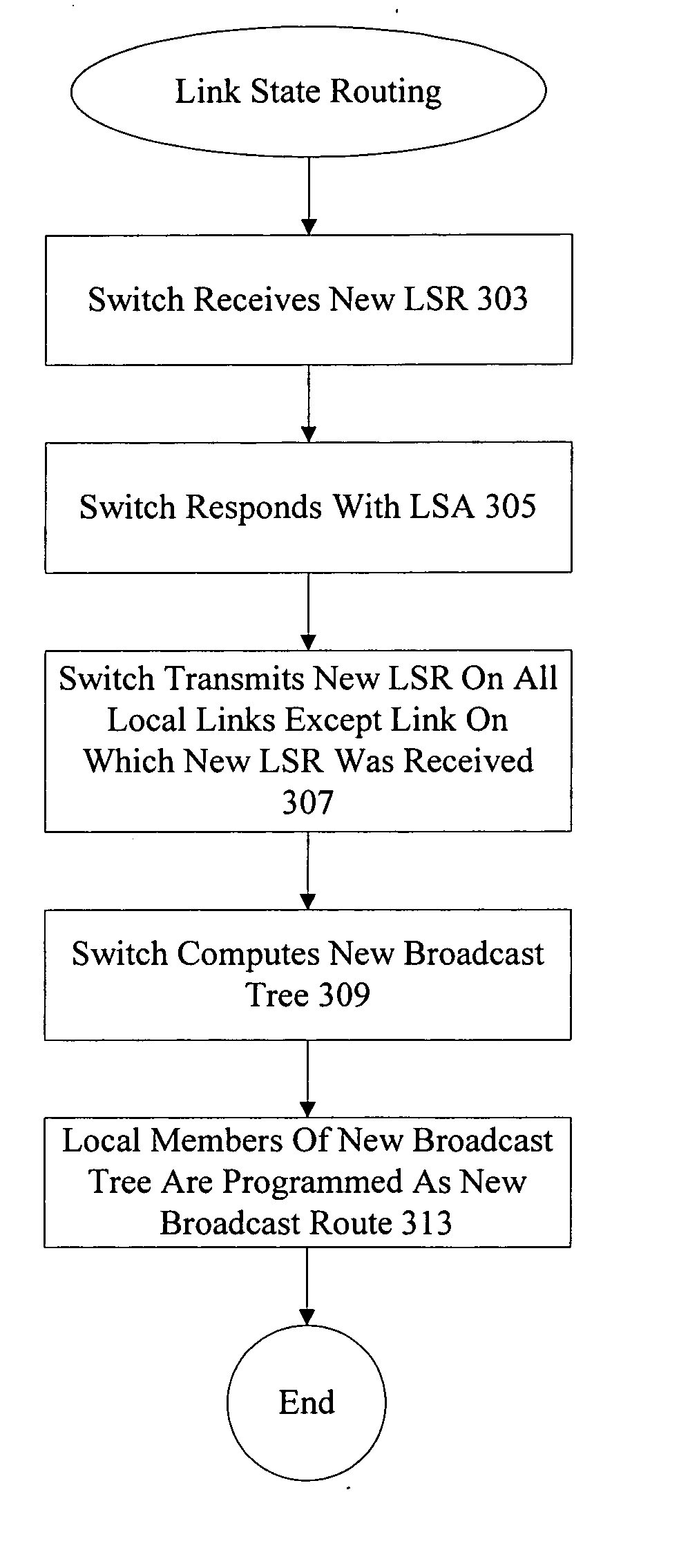
[0022] Reference will now be made in detail to some specific embodiments of the invention including the best modes contemplated by the inventors for carrying out the invention. Examples of these specific embodiments are illustrated in the accompanying drawings. While the invention is described in conjunction with these specific embodiments, it will be understood that it is not intended to limit the invention to the described embodiments. On the contrary, it is intended to cover alternatives, modifications, and equivalents as may be included within the spirit and scope of the invention as defined by the appended claims.

[0023] For example, the techniques of the present invention will be described in the context of the link state routing for fibre channel and Data Center Ethernet (DCE). However, it should be noted that the techniques of the present invention can be applied to different variations and flavors of fibre channel and DCE as well as to other networks that use link state rou...


PUM


Abstract

According to the present invention, methods and apparatus are provided to improve the link state routing protocol (LSRP) to prevent transient loops during topology changes. Broadcast and shared multicast traffic is dropped upon detecting link state change until neighboring nodes have computed routes using updated link state information. An acknowledgment for a link state record is sent only after route computation is complete using updated link state information.

Description

BACKGROUND OF THE INVENTION [0001] 1. Field of the Invention. [0002] The present invention generally relates to the link state routing protocol. More specifically, the present invention provides techniques and mechanisms for improving the link state routing protocol to prevent formation of transient loops. [0003] 2. Description of Related Art [0004] Link state routing is a protocol that allows a node in a network to determine network topology by sharing information about transmission cost to each of its neighboring nodes. Link state routing packets are transmitted to neighbors and link state routing packets are received from neighbors. With the shared link state information, the least expensive paths to various destinations can be determined. [0005] In broadcast or shared multicast networks, link state routing allows a network to generate a broadcast or shared multicast tree. However, transient loops can sometimes arise when network topology changes because neighboring nodes may not...

Claims


Application Information

Patent Timeline
Patent Type & Authority Applications(United States)
IPC IPC(8): H04L12/28H04L12/56
CPCH04L45/02H04L45/16H04L45/18H04L45/48H04L45/60H04L45/03H04L45/484
Inventor JAIN, SACHINMELLACHERUVU, RAMANA
Owner CISCO TECH INC
Why Eureka
Try Eureka