Polishing apparatus and polishing method

Inactive Publication Date: 2007-06-14
EBARA CORP
View PDF8 Cites 35 Cited by
  • Summary
  • Abstract
  • Description
  • Claims
  • Application Information

AI Technical Summary

Benefits of technology

[0036] According to the present invention described above, polishing can be perf

Problems solved by technology

However, a polishing rate (removal rate) of the surface of the substrate is affected not only by contact pressure acting between the substrate and the polishing surface, but also by a temperature of the polishing surface, a concentration of the polishing liquid (i.e., slurry) to be supplied, and the like.
Accordingly, adjustment of the contact pressure is not enough to completely control the removal rate.
Particularly, in a CMP process in which a removal rate greatly depends on a temperature of the polishing surface (for example, in a case where a surface hardness of a polishing cloth greatly depends on a temperature thereof), the removal rate would vary from area to area of the surface of the substrate depending on a temperature distribution, and as a result, a uniform polishing profile cannot be obtained.
Generally, the temperature distribution of

Method used


Image

  • Polishing apparatus and polishing method
  • Polishing apparatus and polishing method
  • Polishing apparatus and polishing method

Examples


experimental example

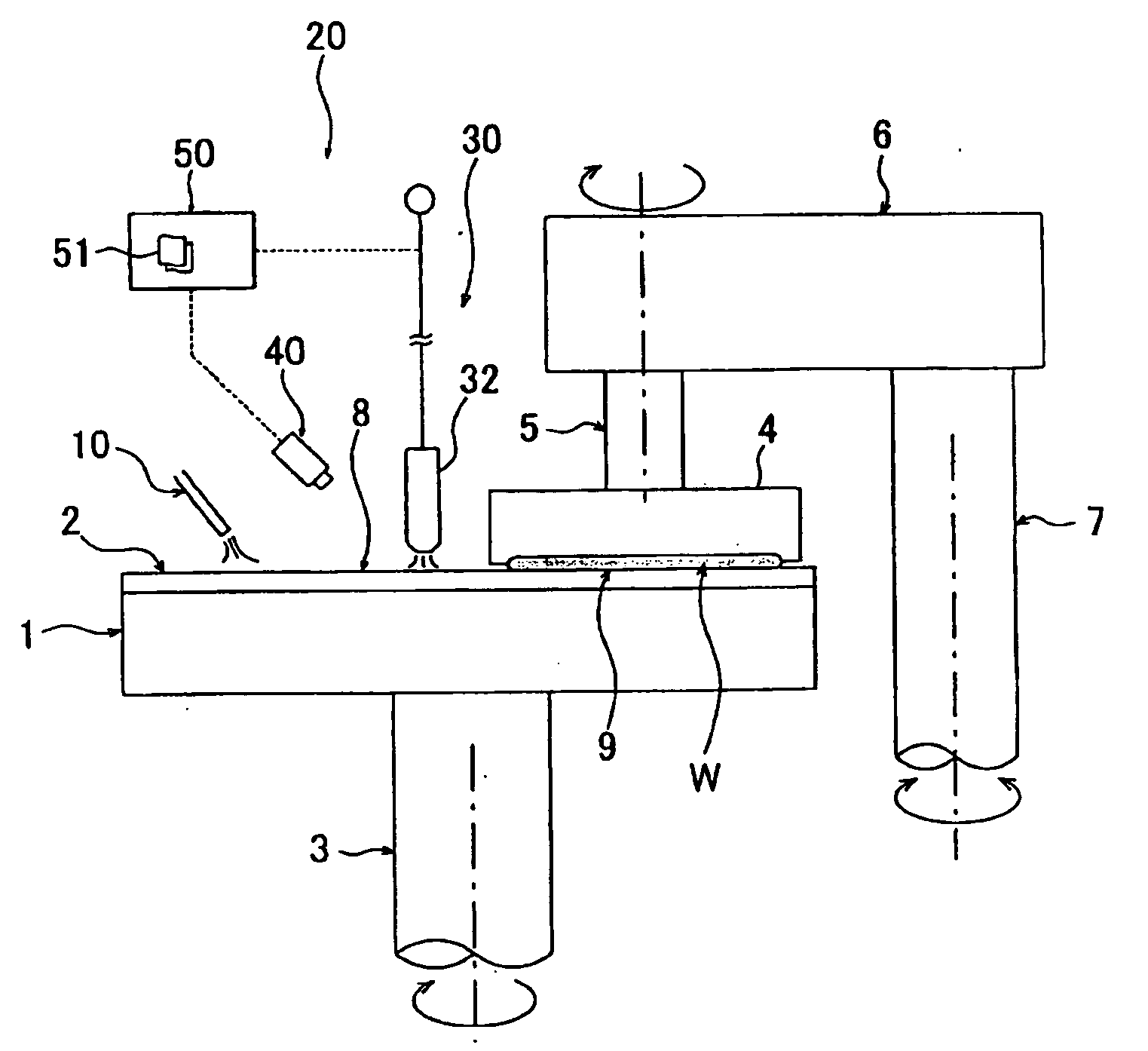
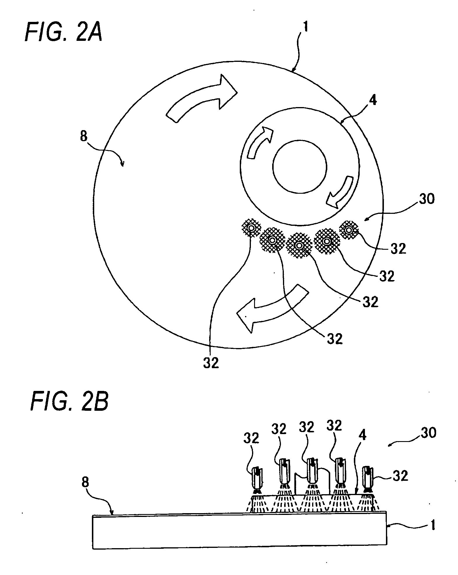
[0068] Next, an experimental example of the present invention will be described with reference to FIGS. 7A and 7B. FIG. 7A is a view showing the polishing table 1 as viewed from above, and FIG. 7B is a graph showing a polishing profile of the polished surface of the substrate W. More specifically, FIG. 7B shows comparison of the polishing profile between a case where the polishing surface 8 was not heated or cooled (i.e., the temperature distribution of the polishing surface 8 was not adjusted) during polishing and a case where predetermined portions (indicated by symbol “A” in FIG. 7A) of the polishing surface 8 were cooled during polishing.

[0069] Cooling of the polishing surface 8 was performed by ejecting the gas only from the ejection nozzles 32 that are arranged at locations corresponding to the portions A of the polishing surface 8 of the polishing apparatus according to the above embodiment. In FIG. 7B, a horizontal axis shows measurement position on the surface 9 (indicated...


PUM

PropertyMeasurementUnit
Temperatureaaaaaaaaaa
Flow rateaaaaaaaaaa
Timeaaaaaaaaaa

Abstract

A polishing apparatus polish a surface of a substrate, such as a semiconductor substrate. The polishing apparatus according to the present invention includes a substrate holding mechanism, a polishing table having a polishing surface, and a polishing surface temperature controller for controlling a temperature distribution of the polishing surface. The substrate holding mechanism and the polishing table are operable to provide relative movement between the surface of the substrate and the polishing surface while the substrate holding mechanism presses the surface of the substrate against the polishing surface to thereby polish the surface of the substrate. The polishing surface temperature controller controls the temperature distribution so that the polishing surface has a predetermined temperature distribution to thereby control removal rates of portions of the surface of the substrate.

Description

BACKGROUND OF THE INVENTION [0001] 1. Field of the Invention [0002] The present invention relates to a polishing apparatus and a polishing method for polishing a substrate, such as a semiconductor substrate, by operating a substrate holding mechanism so as to bring the substrate into contact with a polishing surface of a polishing table and by providing relative movement between a surface of the substrate and the polishing surface. [0003] 2 . Description of the Related Art [0004] A chemical mechanical polishing (CMP) apparatus has been known as an apparatus for polishing a substrate, e.g., a semiconductor substrate. This type of polishing apparatus includes a polishing table, a polishing cloth (polishing pad), and a substrate holding mechanism (top ring) for holding a substrate. The polishing cloth is attached to an upper surface of the polishing table to form a polishing surface. A substrate to be polished (hereinafter referred to as a substrate), such as a semiconductor substrate,...

Claims


Application Information

Patent Timeline
IPC IPC(8): B24B51/00B24B1/00B24B37/013B24B37/015B24B49/14H01L21/304
CPCB24B37/015B24B37/04B24B49/14H01L21/304
Inventor NABEYA, OSAMU
Owner EBARA CORP
Why Eureka
Try Eureka