
Polishing apparatus and polishing method
a technology of polishing apparatus and polishing method, which is applied in the direction of grinding machine components, manufacturing tools, lapping machines, etc., can solve the problems of insufficient adjustment of contact pressure to completely control the removal rate, affecting the polishing rate of the surface of the substrate, and unable to achieve uniform polishing profiles
- Summary
- Abstract
- Description
- Claims
- Application Information
AI Technical Summary
Benefits of technology
Problems solved by technology
Method used
Image

Examples
experimental example
[0068] Next, an experimental example of the present invention will be described with reference to FIGS. 7A and 7B. FIG. 7A is a view showing the polishing table 1 as viewed from above, and FIG. 7B is a graph showing a polishing profile of the polished surface of the substrate W. More specifically, FIG. 7B shows comparison of the polishing profile between a case where the polishing surface 8 was not heated or cooled (i.e., the temperature distribution of the polishing surface 8 was not adjusted) during polishing and a case where predetermined portions (indicated by symbol “A” in FIG. 7A) of the polishing surface 8 were cooled during polishing.
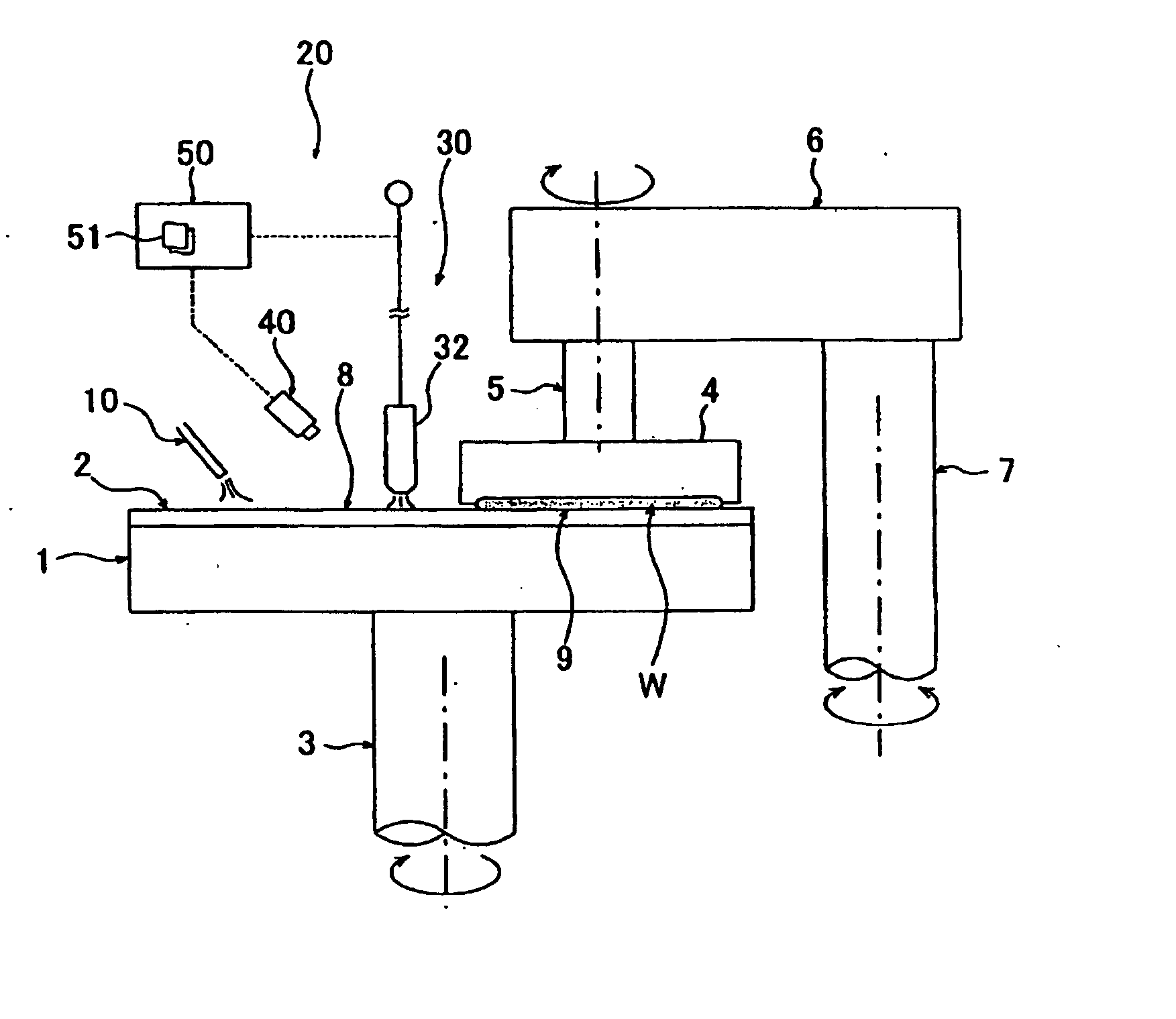
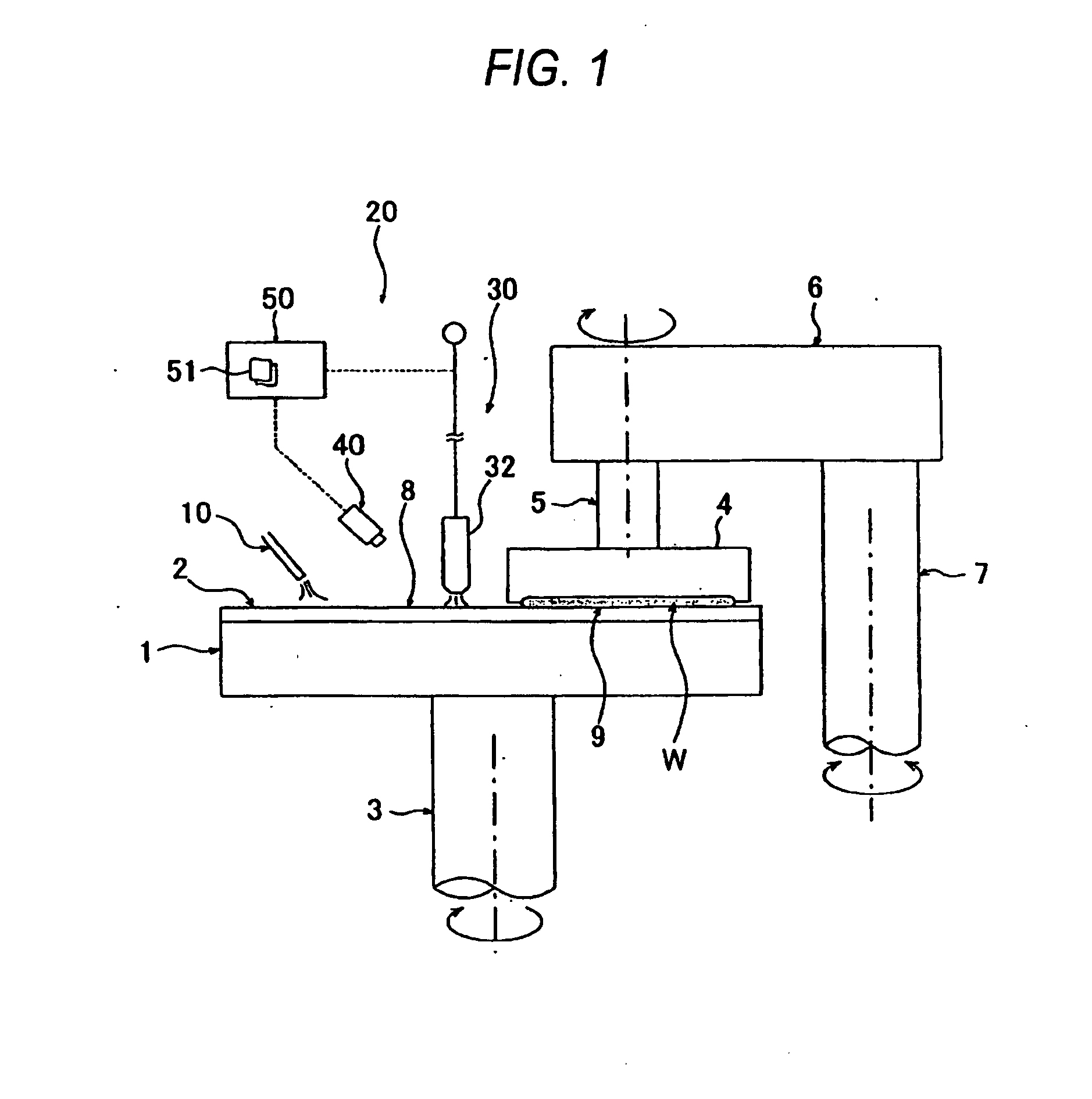
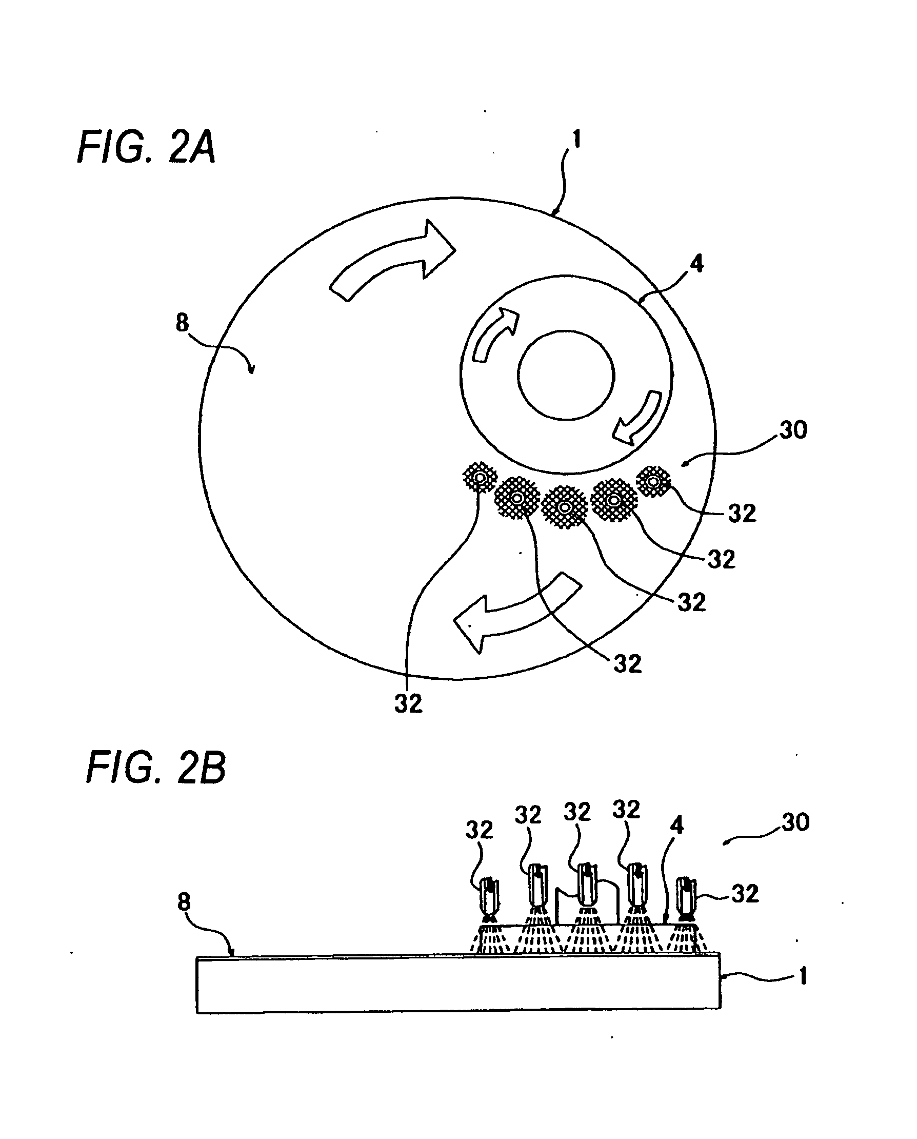
[0069] Cooling of the polishing surface 8 was performed by ejecting the gas only from the ejection nozzles 32 that are arranged at locations corresponding to the portions A of the polishing surface 8 of the polishing apparatus according to the above embodiment. In FIG. 7B, a horizontal axis shows measurement position on the surface 9 (indicated...
PUM
 Abstract
Description
Claims
Application Information