Seal section oil seal for submersible pump assembly

a submersible pump and oil seal technology, applied in the direction of piston pumps, positive displacement liquid engines, borehole/well accessories, etc., can solve the problems of adding cost and additional length to equipmen

Inactive Publication Date: 2007-06-21
BAKER HUGHES INC
View PDF25 Cites 74 Cited by
  • Summary
  • Abstract
  • Description
  • Claims
  • Application Information

AI Technical Summary

Benefits of technology

[0006] Preferably, an oil is filled in the space between the secondary and primary seals to provide lubrication for the primary seal. The oil may be a type that is more resistant to emulsifying with water than the motor lubricant or ...

Problems solved by technology

Even though the leakage rate is very small, well fluid will ingress into the motor over ...

Method used


Image

  • Seal section oil seal for submersible pump assembly
  • Seal section oil seal for submersible pump assembly
  • Seal section oil seal for submersible pump assembly

Examples


Embodiment Construction

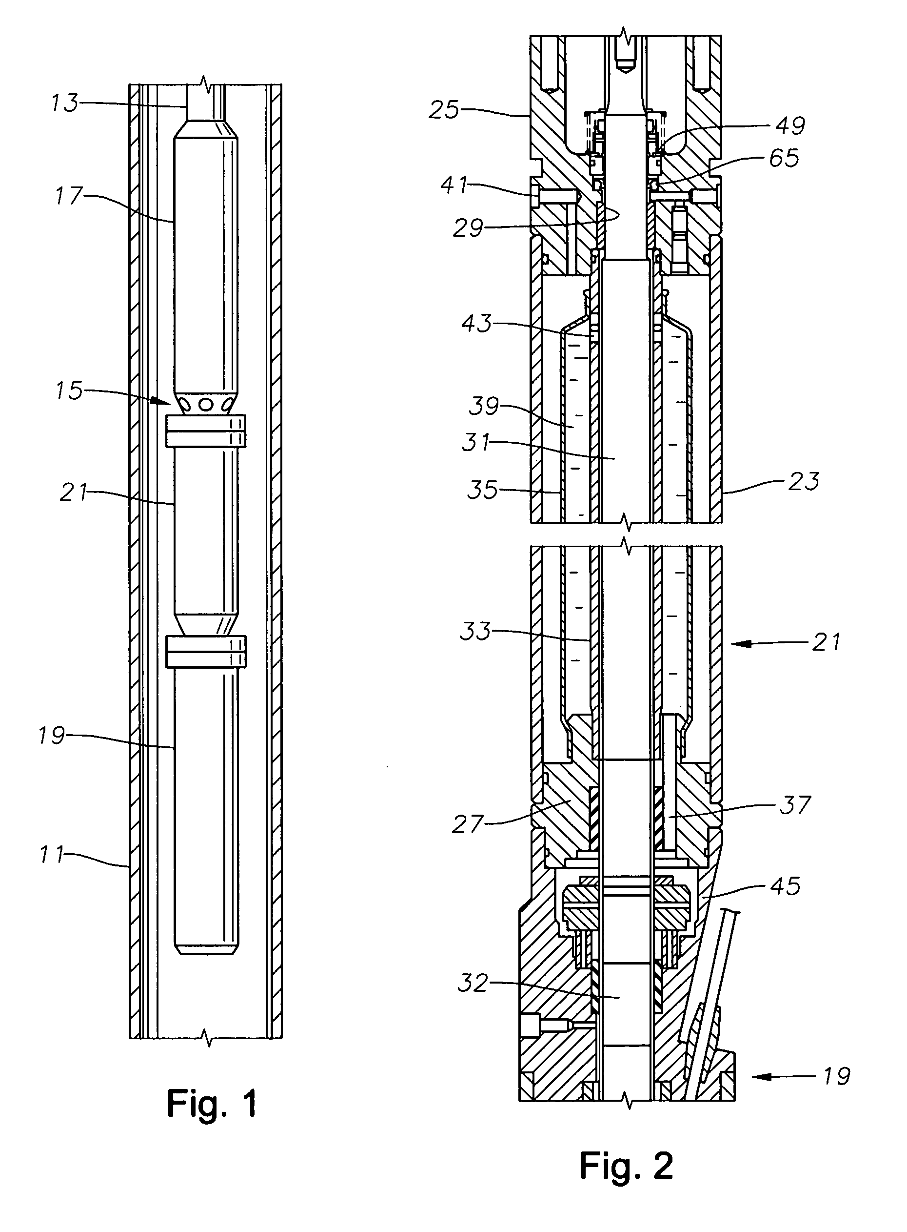
[0010] Referring to FIG. 1, the well has a casing 11 that has perforations for entry of well fluid. A string of production tubing 13 extends into the well. An electrical submersible pump assembly 15 is secured to tubing 13 and suspended therefrom.

[0011] Electrical submersible pump assembly 15 includes a rotary pump 17 that in the embodiment shown, comprises a centrifugal pump having a plurality of stages. Each stage has a rotating impeller and a stationary diffuser (not shown). Alternately, pump 17 could be another type, such as a progressing cavity pump. In a progressing cavity pump, a helical rotor rotates within a stationary elastomeric stator having a double helical bore.

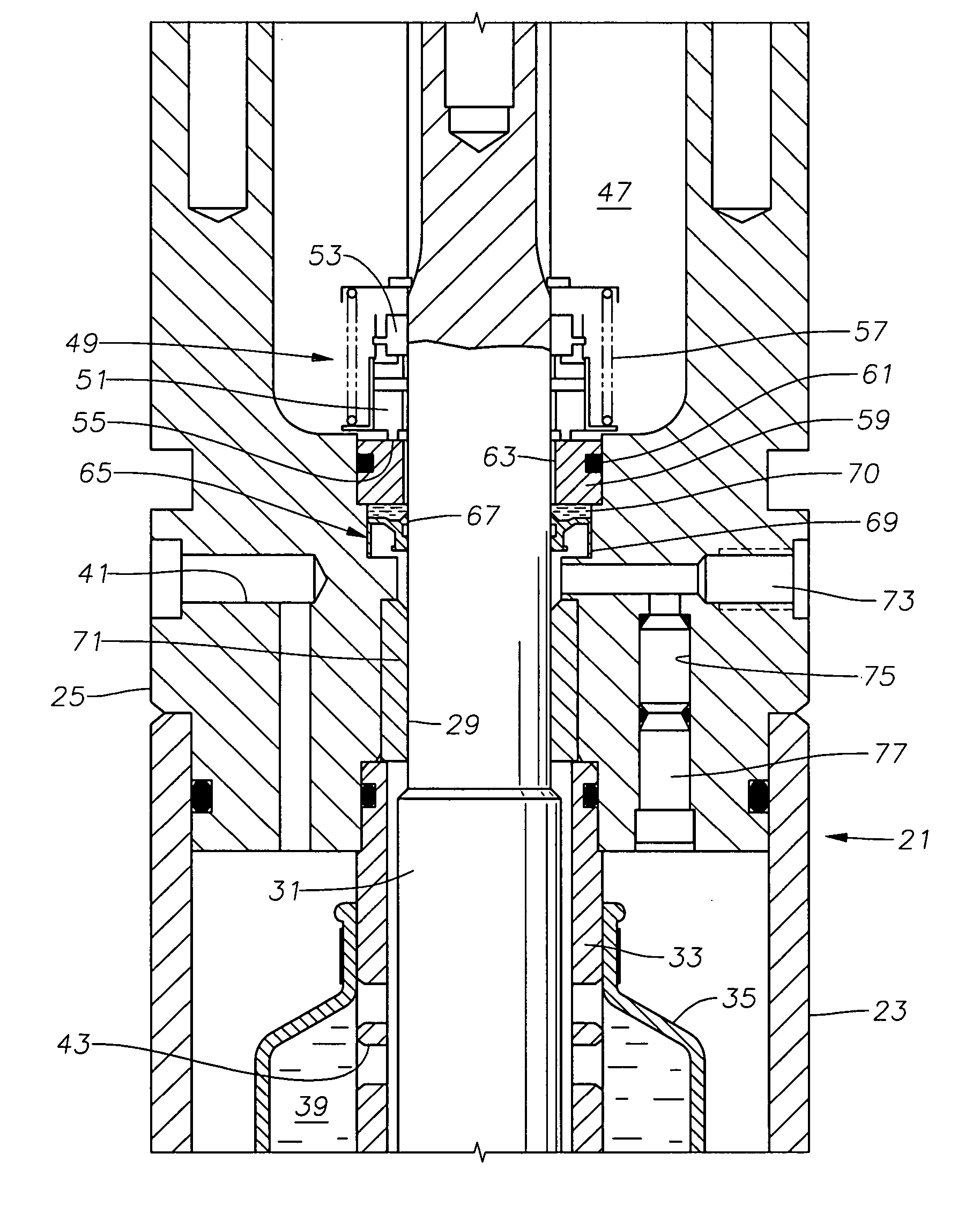
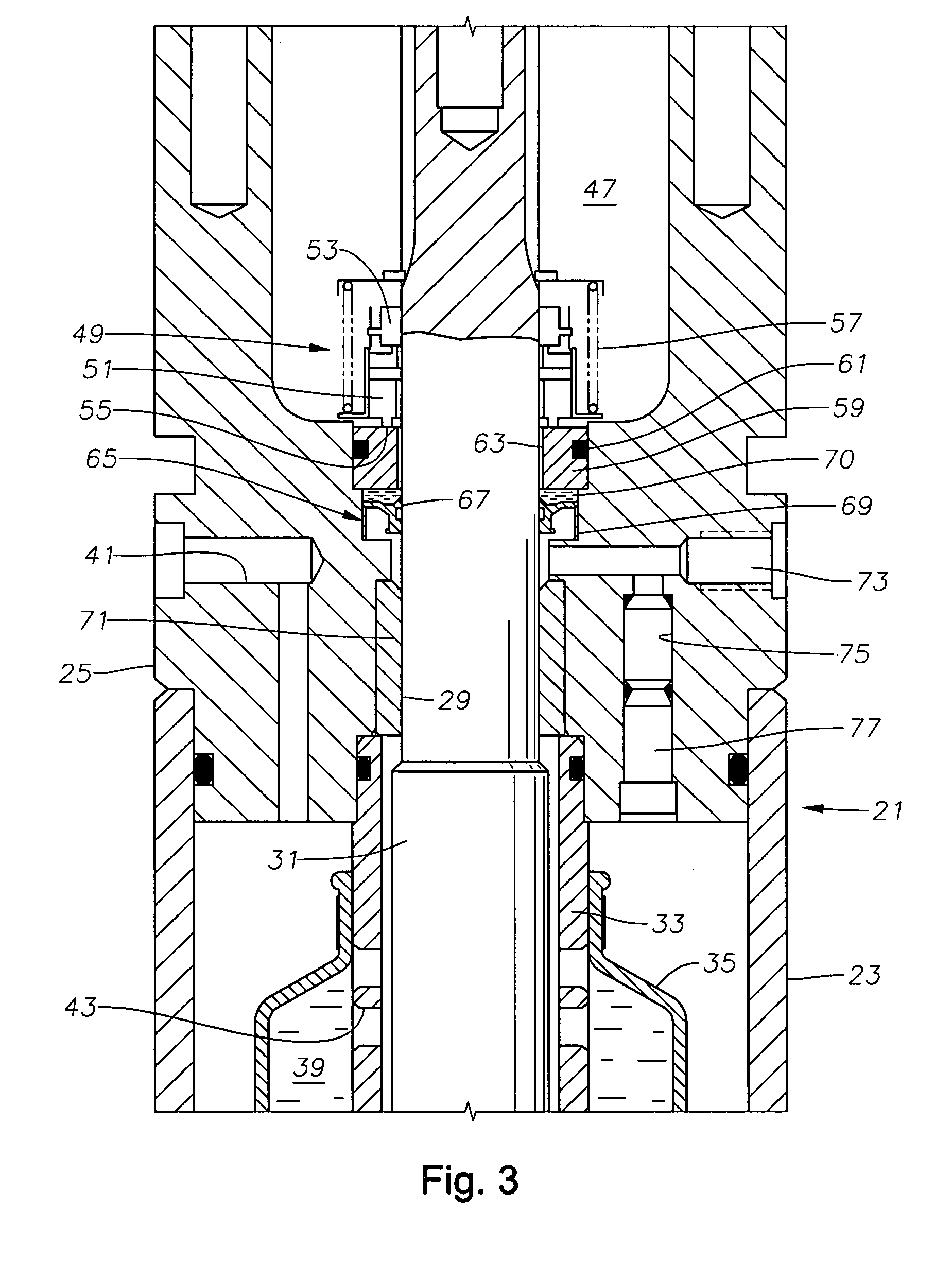
[0012] Pump 17 is driven by a motor 19, which is typically an AC electrical motor. A seal section 21 extends between pump 17 and motor 19. Seal section 21 serves to equalize the pressure of lubricant contained in motor 19 with the pressure of the well bore fluid. Referring to FIG. 2, seal section 21 has a hous...


PUM


Abstract

A seal section for location between a submersible rotary pump and motor has a primary mechanical seal and a secondary oil seal at the pump end of the seal section. The mechanical seal has rigid seal faces that slide in engagement with each other. The secondary seal has an inner portion that seals against the shaft of the seal section and an outer portion that seals against the housing. The seal section has a pressure equalizing device for equalizing pressure of motor lubricant with well bore pressure.

Description

FIELD OF THE INVENTION [0001] This invention relates in general to submersible well pump assemblies, and in particular to a seal section located between the motor and the pump for equalizing the pressure of lubricant within the motor with well bore pressure. BACKGROUND OF THE INVENTION [0002] A typical submersible well pump assembly of the type concerned herein has an electrical motor that is connected to a centrifugal pump by a seal section. The motor is filled with a dielectric lubricant for lubricating bearings within. The seal section has a pressure equalizing device, which may be a bladder or a U-tube arrangement, for equalizing the pressure of the lubricant in the motor with the well bore fluid on the exterior. [0003] The seal section has a shaft that couples to the motor shaft on one end and to the pump shaft on the other end. A mechanical seal between the housing of the seal section and the shaft reduces encroachment of well bore fluid into contact with the lubricant in the ...

Claims


Application Information

Patent Timeline
IPC IPC(8): F04B17/00
CPCF04D13/10F04D29/126E21B43/128
Inventor PARMETER, LARRY J.HALL, CLARENCE F.
Owner BAKER HUGHES INC
Why Eureka
Try Eureka