Eureka AIR delivers breakthrough ideas for toughest innovation challenges, trusted by R&D personnel around the world.

Method and Apparatus for Forming a Mono-Diameter Wellbore Casing

Inactive Publication Date: 2007-06-28
ENVENTURE GLOBAL TECH LLC
View PDF99 Cites 5 Cited by
  • Summary
  • Abstract
  • Description
  • Claims
  • Application Information

AI Technical Summary

Benefits of technology

[0043] According to another aspect of the present invention, a method of forming a structure having desired strength characteristics is provided that includes providing a first tubular member, and plastically deforming and radially expanding additional tubular members onto the interior surface of the first tubular member until the desired strength characteristics are achieved.
[0044] According to another aspect of t

Problems solved by technology

Such a large borehole diameter involves increased costs due to heavy casing handling equipment, large drill bits and increased volumes of drilling fluid and drill cuttings.
Moreover, increased drilling rig time is involved due to required cement pumping, cement hardening, required equipment changes due to large variations in hole diameters drilled in the course of the well, and the large volume of cuttings drilled and removed.

Method used


Image

  • Method and Apparatus for Forming a Mono-Diameter Wellbore Casing
  • Method and Apparatus for Forming a Mono-Diameter Wellbore Casing
  • Method and Apparatus for Forming a Mono-Diameter Wellbore Casing

Examples


Embodiment Construction

[0118] Several embodiments of methods and apparatus for forming a mono-diameter wellbore casing are disclosed. In several alternative embodiments, the methods and apparatus may be used for form or repair mono-diameter wellbore casings, pipelines, or structural supports. Furthermore, while the present illustrative embodiments are described with reference to the formation of mono-diameter wellbore casings, the teachings of the present disclosure have general application to the formation or repair of wellbore casings, pipelines, and structural supports.

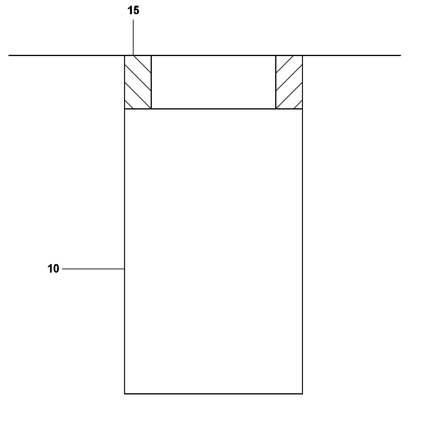
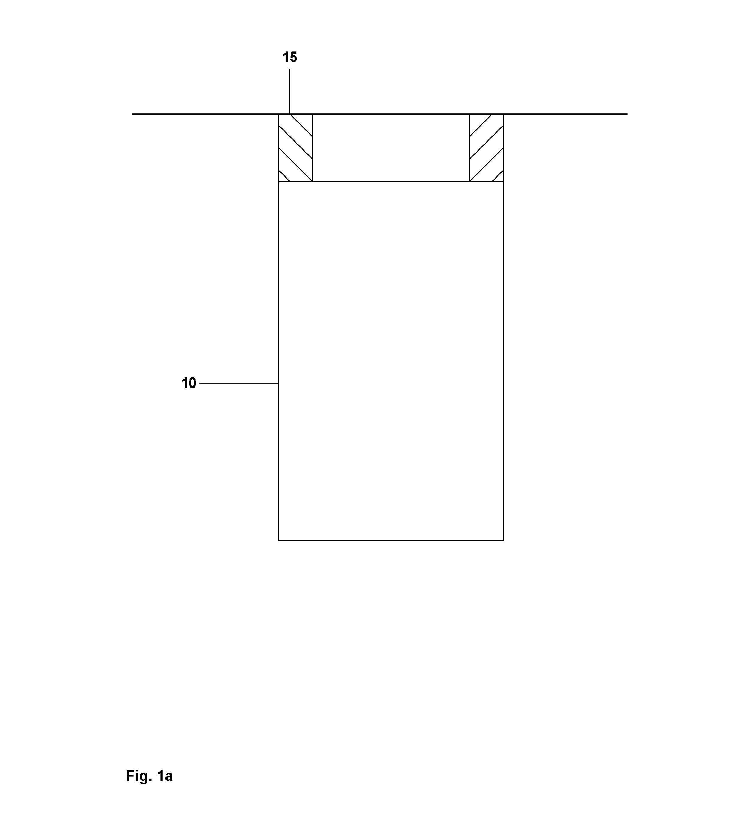
[0119] Referring initially to FIG. 1a, a wellbore 10 includes a preexisting wellbore casing 15. The wellbore 10 may be oriented in any orientation from the vertical to the horizontal. The preexisting wellbore casing 15 may be coupled to the upper portion of the wellbore 10 using any number of conventional methods. In a preferred embodiment, the wellbore casing 15 is coupled to the upper portion of the wellbore 10 using one or more of th...


PUM

PropertyMeasurementUnit
Diameteraaaaaaaaaa
Deformation enthalpyaaaaaaaaaa

Abstract

A mono-diameter wellbore casing. The mono-diameter wellbore casing is formed by plastically deforming and radially expanding a first tubular member within a wellbore. A second tubular member is then plastically deformed and radially expanded in overlapping relation to the first tubular member. The second tubular member and the overlapping portion of the first tubular member are then radially expanded again.

Description

CROSS REFERENCE TO RELATED APPLICATIONS [0001] This application is a continuation of U.S. patent application Ser. No. 11 / 074,266, attorney docket no. 25791.358, filed on Mar. 7, 2005, which is a divisional of U.S. application Ser. No. 10 / 465,831, filed Jun. 13, 2003, attorney docket no. 25791.52.06 (now allowed), which is the National Phase of the International Application No. PCT / US02 / 00093, attorney docket number 25791.52.02 which is based on U.S. Application Ser. No. 60 / 259,486, attorney docket number 25791.52, filed on Jan. 3, 2001, which was a Continuation-In-Part of U.S. application Ser. No. 10 / 406,648 filed Mar. 31, 2003, attorney docket no. 25791.48.06 (now allowed), which is a National Phase of the International Application No. PCT / US01 / 30256, attorney docket number 25791.48.02 which is based on U.S. Application Ser. No. 60 / 237,334, filed on Oct. 2, 2000, attorney docket number 25791.48, the disclosures of which are incorporated herein by reference. [0002] This application ...

Claims


Application Information

Patent Timeline
IPC IPC(8): B23P21/00E21B43/10
CPCY10T29/53065E21B43/105
Inventor COOK, ROBERT LANCERING, LEVZWALD, EDWIN A. JR.FILIPPOV, ANDREI GREGORYWADDELL, KEVIN K.
Owner ENVENTURE GLOBAL TECH LLC
Why Eureka
Eureka Blog
Learn More