Valve timing control device

Active Publication Date: 2007-06-28
AISIN SEIKI KK
View PDF1 Cites 30 Cited by
  • Summary
  • Abstract
  • Description
  • Claims
  • Application Information

AI Technical Summary

Benefits of technology

[0008] According to an aspect of the present invention, a valve timing control device includes a driving side rotational member synchronously rotatable with a crankshaft of an internal combustion engine, a driven side rotational member arranged coaxially with the driving side rotational member and synchronously rotatable with a camshaft that controls an opening and closing operation of valves of the internal combustion engine, a retarded angle chamber defmed by the driving side rotational member and the driven side rotational member and displacing a relative rotational phase of the driven side rotational member to the driving side rotational member in a retarded angle direction by a supply of a fluid to the retarded angle chamber, an advanced angle chamber defined by the driving side rotational member and the driven side rotational member and displacing the relative rotational phase in an advanced angle direction by the supply of the fluid to the advanced angle chamber, a fluid supply and discharge mechanism for supplying the fluid to the advanced angle chamber and the retarded angle chamber and for discharging the fluid from the advanced angle chamber and the retarded angle chamber, a lock mechanism for locking the relative rotational phase at a predetermined lock phase, and a phase displacement restriction mechanism operable separately from the lock mechanism and switching the relative rotational phase between a restricted state in which a displacement of the relative rotational phase is restricted within a predetermined phase displacement allowable range and an unrestricted state in which the restricted state is released. The phase displacement restriction mechanism includes a recess portion and an insertion member inserted into the recess portion so as to achieve the restricted state and retraced from the recess portion so as to achieve the unrestricted state, the recess portion provided at one of the driving side rotational member and the driven side rotational member, the insertion member provided at the other one of the driving side rotational member and the driven side rotational member, the insertion member biased to be inserted into the recess portion. The valve timing control device further includes a retention mechanism for retaining the phase displacement restriction mechanism in the unrestricted state in which the insertion member is retracted from the recess portion.

Problems solved by technology

However, according to the aforementioned valve timing control device, the relative rotation can be only locked at the single predetermined lock phase and may not be locked at the different phase.

Method used


Image

  • Valve timing control device
  • Valve timing control device
  • Valve timing control device

Examples


first embodiment

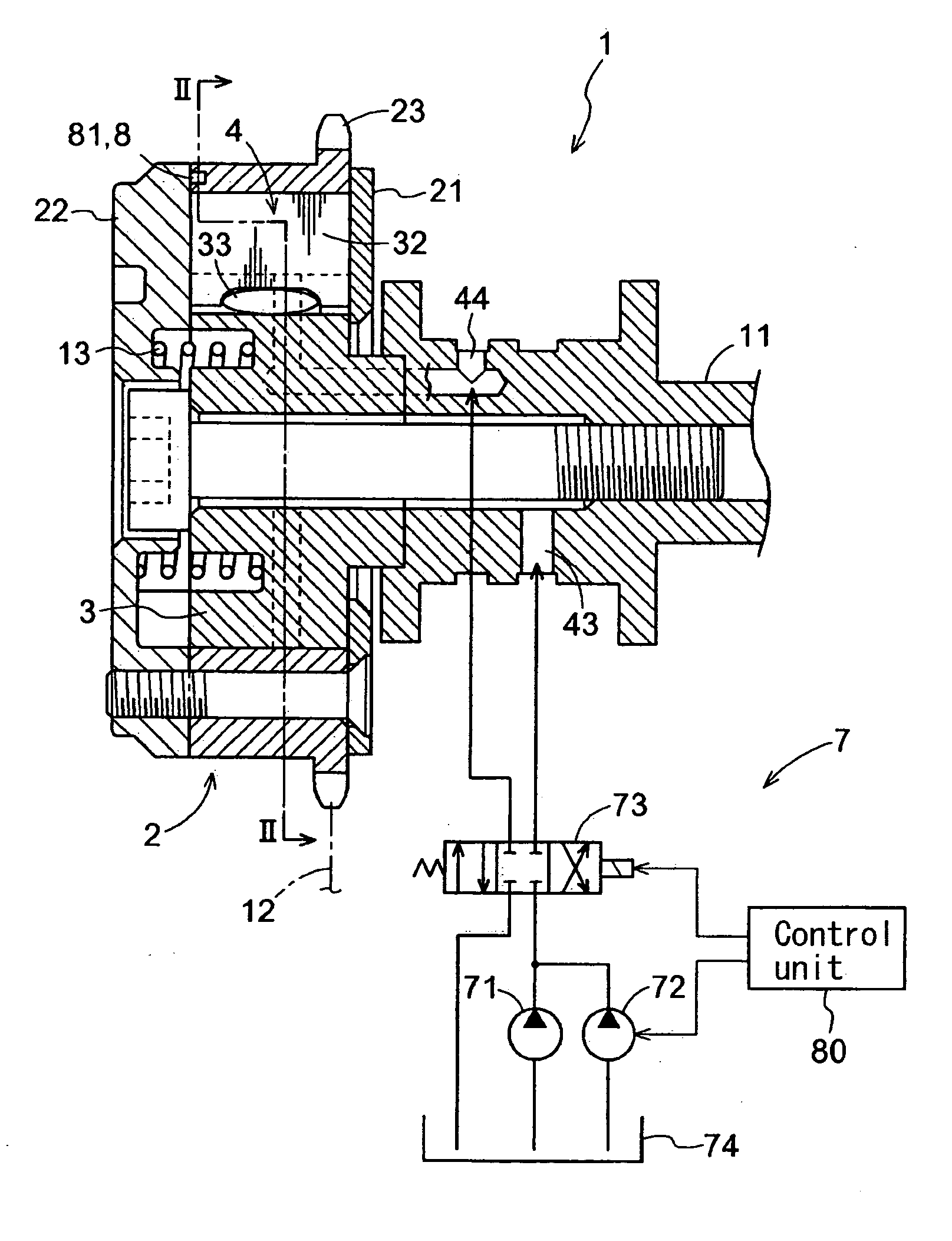
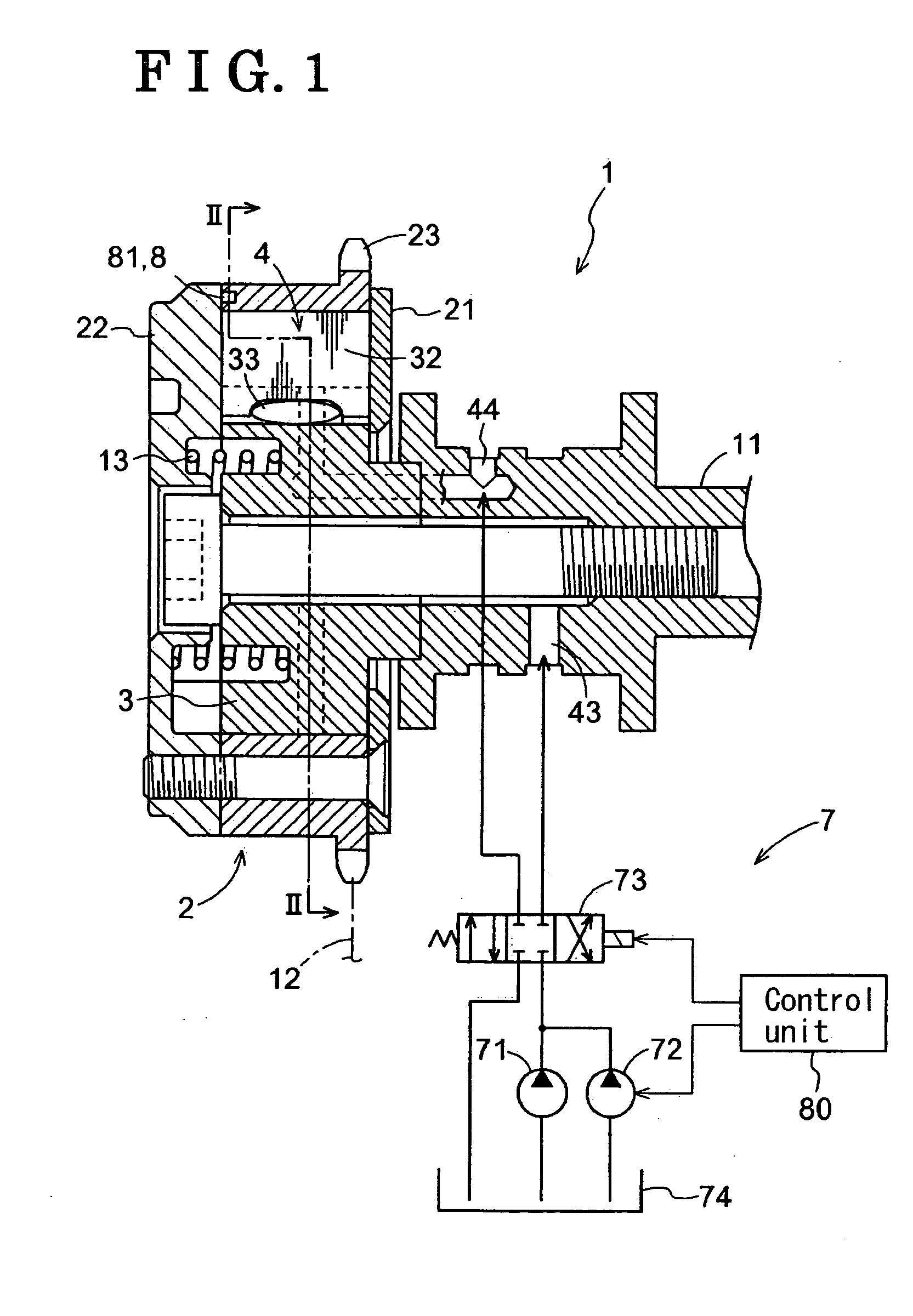
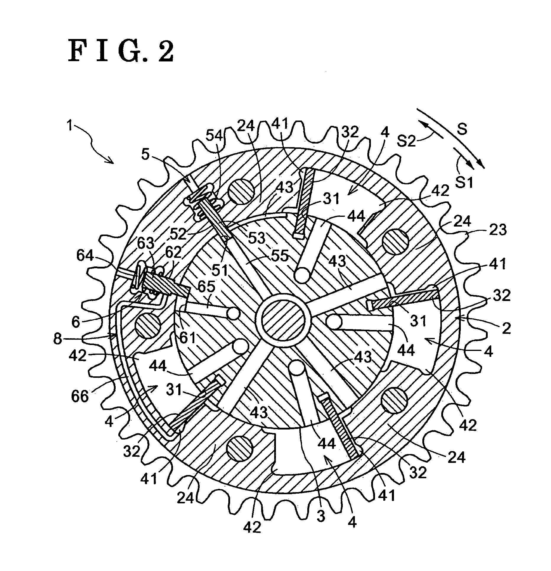
[0033] the present invention will be explained with reference to the attached drawings. FIG. 1 is a cross-sectional side view illustrating an overall structure of a valve timing control device. FIGS. 2 to 6 are cross-sectional views taken along the line II-II in FIG. 1 and showing each status of the valve timing control device. FIG. 7 is an enlarged view of a phase displacement restriction mechanism and a retention mechanism. FIG. 23 is a view illustrating the structure of the valve timing control device.

[0034] A valve timing control device 1 includes an outer rotor 2 serving as a driving side rotational member and an inner rotor 3 serving as a driven side rotational member. The outer rotor 2 is synchronously rotatable with a crankshaft 15 of an engine 10 serving as an internal combustion engine. The inner rotor 3 is arranged coaxially with the outer rotor 2 and synchronously rotatable with a camshaft 11.

[0035] The inner rotor 3 is integrally attached to an end portion of the camsh...

third embodiment

[0070] The valve mechanism 9 is provided at the restriction passage 65 communicating with the retarded angle passages 44 and the retarded angle chambers 42. The valve mechanism 9 turns to an open state when a portion of the operating oil, which is supplied to the advanced angle chambers 41, is supplied to the valve mechanism 9, and also retains the open state when a portion of the operating oil, which is supplied to at least one of the advanced angle chambers 41 and the retarded angle chambers 42, is supplied to the valve mechanism 9. The restriction passage 65 is constituted so that a portion of the operating oil supplied to the retarded angle chambers 42 is supplied to the restricting recess portion 61. the retarded angle chamber 42 corresponds to one of the advanced angle chamber and the retarded angle chamber, and the advanced angle chamber 41 corresponds to the other one of the advanced angle chamber and the retarded angle chamber.

[0071] As illustrated in FIG. 18, the valve me...

second embodiment

[0088] According to the aforementioned second embodiment, the retention mechanism 8 includes the engaging member 83 movable in the rotation direction and the radial direction of the outer rotor 2 and the inner rotor 3, and the guide surface 84a radially outwardly guiding the engaging member 83 so that the engaging member 83 moves close to the engaged portion 67a. However, the retention mechanism 8 is not limited to the above structure.

[0089] According to the aforementioned third embodiment, the retarded angle chamber 42 corresponds to one of the advanced angle chamber and the retarded angle chamber, and the advanced angle chamber 41 corresponds to the other one of the advanced angle chamber and the retarded angle chamber. However, the advanced angle chamber 41 can correspond to one of the advanced angle chamber and the retarded angle chamber and the retarded angle chamber 42 can correspond to the other one of the advanced angle chamber and the retarded angle chamber.

[0090] The afor...


PUM


Abstract

A valve timing control device includes a driving side rotational member synchronously rotatable with a crankshaft of an internal combustion engine, a driven side rotational member synchronously rotatable with a camshaft that controls an opening and closing operation of valves of the internal combustion engine, a retarded angle chamber, an advanced angle chamber, a fluid supply and discharge mechanism, a lock mechanism for locking the relative rotational phase at a predetermined lock phase, a phase displacement restriction mechanism switching the relative rotational phase between a restricted state and an unrestricted state, the phase displacement restriction mechanism includes a recess portion and an insertion member so as to achieve the restricted state and the unrestricted state, and a retention mechanism for retaining the phase displacement restriction mechanism in the unrestricted state in which the insertion member is retracted from the recess portion.

Description

CROSS REFERENCE TO RELATED APPLICATIONS [0001] This application is based on and claims priority under 35 U.S.C. § 119 to Japanese Patent Application Nos. 2005-375614 and 2006-123302, filed on Dec. 27, 2005 and Apr. 27, 2006, respectively, the entire content of which is incorporated herein by reference. FIELD OF THE INVENTION [0002] This invention generally relates to a valve timing control device. BACKGROUND [0003] A known valve timing control device includes a driving side rotational member synchronously rotatable with a crankshaft of an internal combustion engine, a driven side rotational member arranged coaxially with the driving side rotational member and synchronously rotatable with a camshaft that controls an opening and closing operation of valves of the internal combustion engine, a retarded angle chamber defmed by the driving side rotational member and the driven side rotational member and displacing a relative rotational phase of the driven side rotational member to the dr...

Claims


Application Information

Patent Timeline
Patent Type & Authority Applications(United States)
IPC IPC(8): F01L1/34
CPCF01L1/022F01L1/024F01L1/3442F01L2001/0537F01L2001/34459F01L2001/34463F01L2001/34466F01L2001/34473F01L2001/34476F01L2001/34483
Inventor SUZUKI, SHIGEMITSUTOMA, NAOTOHASHIZUME, TAKESHI
Owner AISIN SEIKI KK
Why Eureka
Try Eureka