Peelable seal closure assembly

a seal and assembly technology, applied in the field of containers, can solve the problems of increasing the peak peel force, reducing the force required, and reducing the ability of peeling to open the container,

Inactive Publication Date: 2007-06-28
BAXTER INT INC +1
View PDF99 Cites 18 Cited by
  • Summary
  • Abstract
  • Description
  • Claims
  • Application Information

AI Technical Summary

Problems solved by technology

This increased peak peel force is detrimental to use of the multichambered container by making it more difficult to initiate peeling to open the container.
This is especially true for patients using the medical solutions who may be infirmed or elderly and unable to provide the force necessary to initiate peeling.
Moreover, the peak peel force is difficult to control, some containers remaining easy to initiate peeling in the peelable seal, while others becoming almost impossible to initiate by hand.

Method used


Image

  • Peelable seal closure assembly
  • Peelable seal closure assembly
  • Peelable seal closure assembly

Examples


Embodiment Construction

[0053] The present invention is susceptible of embodiments in many different forms. Preferred embodiments of the invention are disclosed with the understanding that the present disclosure is to be considered as exemplifications of the principles of the invention and are not intended to limit the broad aspects of the invention to the embodiments illustrated.

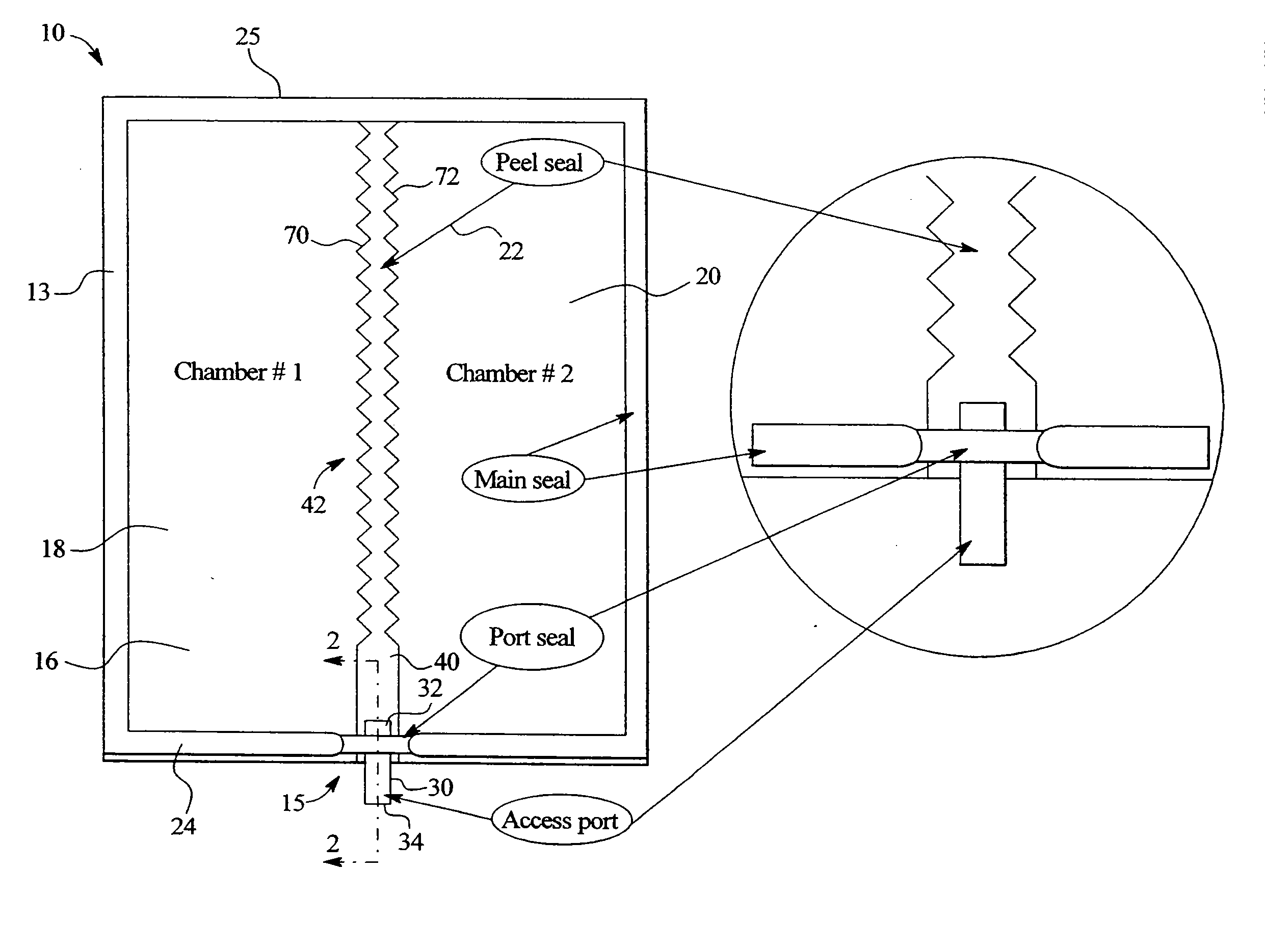
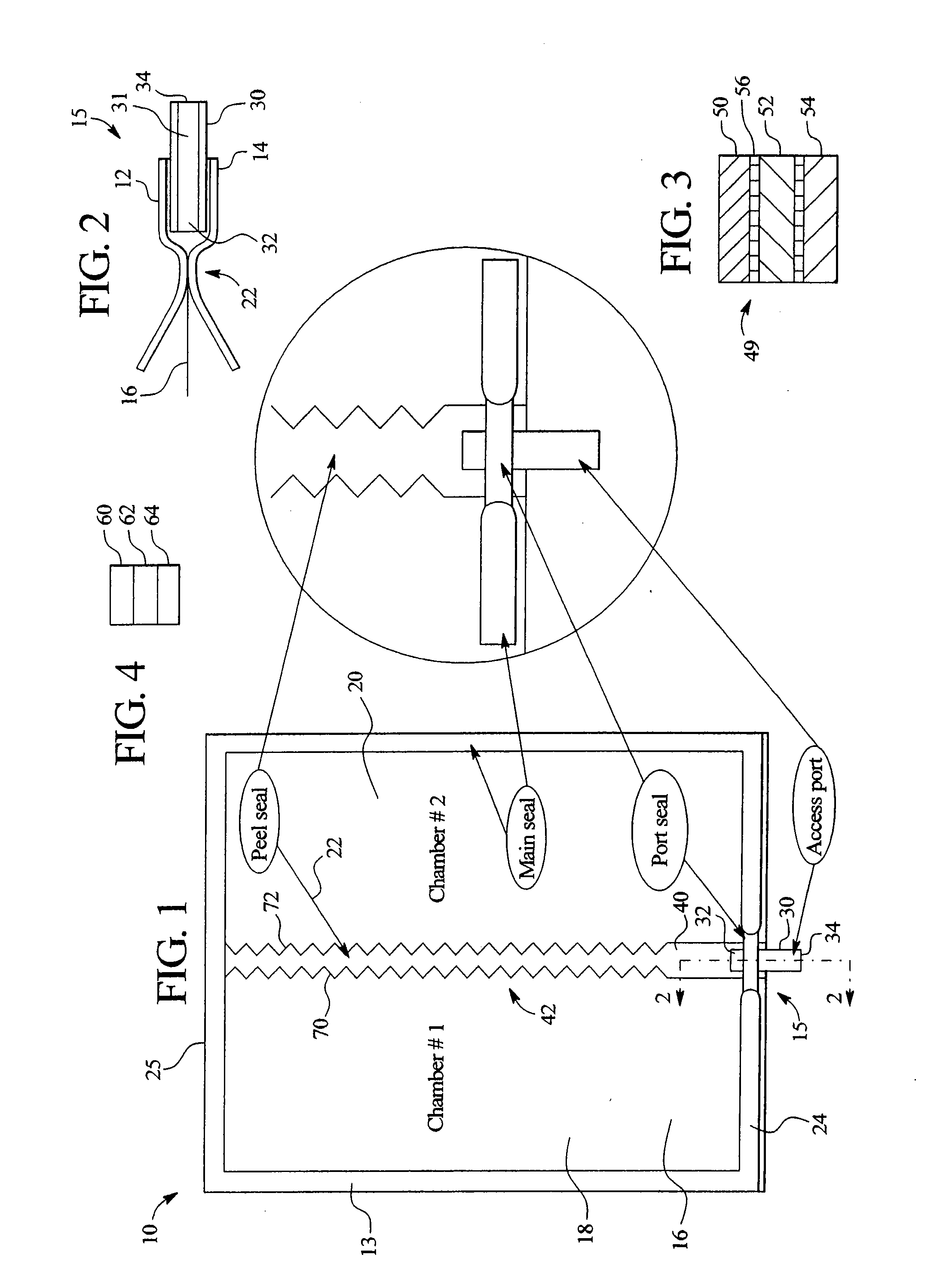
[0054]FIGS. 1 and 2 show container 10 having a first sidewall 12 and a second sidewall 14 having a permanent peripheral seal 13 and a closure assembly 15. The container has a chamber 16 that is divided into a first sub-chamber 18 and a second sub-chamber 20 by a peelable seal 22. The seal 22 extends longitudinally of the container from end seam 24 to end seam 25. The seal is effective in separating components such as two liquids, a solid and a liquid, two gasses, a gas and a liquid and a gas and a solid.

[0055] As best seen in FIG. 2, the closure assembly 15 has a conduit 30 having a fluid flow path 31, a fluid inlet 32 and a flu...


PUM


Abstract

The present invention provides a peelable seal for a multi-chambered container including a first edge and a second edge. At least one of the first edge or second edge includes a stress bearing portion and a non-stress bearing portion.

Description

CROSS-REFERENCE TO RELATED APPLICATIONS [0001] Not Applicable. FEDERALLY SPONSORED RESEARCH OR DEVELOPMENT [0002] Not Applicable. BACKGROUND OF THE INVENTION [0003] The present invention relates to a container for delivering fluids. In particular, it relates to a fluid access assembly for a flowable materials container wherein a conduit of the assembly has an inlet closed by a peel seal structure. The peel seal is activatable by applying fluid pressure to the peel seal structure. This assembly can be used in flowable materials containers and has been found particularly useful with single chamber and multiple chamber medical solution containers. [0004] Multiple chamber containers having sub-chambers separated by a peel seal, frangible seal or other fluid connecting device are widely used to separately store two or more components that are mixed inside the container prior to administering the mixed solution to a patient. The components can be in a powder or liquid form and are typical...

Claims


Application Information

Patent Timeline
Patent Type & Authority Applications(United States)
IPC IPC(8): B65D25/08A61B19/00A61J1/00A61J1/05A61J1/10A61J1/20B65D81/32
CPCA61J1/10A61J1/2093B65D81/3266A61M2207/00A61J2001/2024A61J1/2024A61J1/05A61J1/12
Inventor HOUWAERT, VINCENTGOLLIER, PAUL-ANDRESHANG, SHERWINBALTEAU, PATRICK
Owner BAXTER INT INC
Why Eureka
Try Eureka