Method for a more efficient use of an interface between a smart card and a device, associated smart card and device

a smart card and interface technology, applied in the field of more efficient use of the interface between the smart card and the device, can solve the problems of limited card size and inability to implement the interface on the smart card, and achieve the effect of minimizing the duplication of common-function contacts

Inactive Publication Date: 2007-06-28
LG ELECTRONICS INC
View PDF10 Cites 40 Cited by
  • Summary
  • Abstract
  • Description
  • Claims
  • Application Information

AI Technical Summary

Benefits of technology

[0037] In one embodiment, the invention allows dynamically allocating different functions to contacts, depending on the used application and / or upon card or terminal request. The invention offers the possibility to reallocate the functions of the contacts at any time during a smart card session, and reinitiate the smart card session with another interface configuration and protocol. A contact negotiation phase for instance is enhanced.
[0038] In another embodiment, the invention allows reusing some contacts of the standard physical interface for the use of other interface configurations, minimizing duplication of common-function contacts.

Problems solved by technology

One easily understands that if a rapid transfer protocol and a contactless application must be implemented on the smart card altogether, it is not possible to implement it on a smart card according to FIG. 2.
However, the size of the card is limited.

Method used


Image

  • Method for a more efficient use of an interface between a smart card and a device, associated smart card and device
  • Method for a more efficient use of an interface between a smart card and a device, associated smart card and device
  • Method for a more efficient use of an interface between a smart card and a device, associated smart card and device

Examples


first embodiment

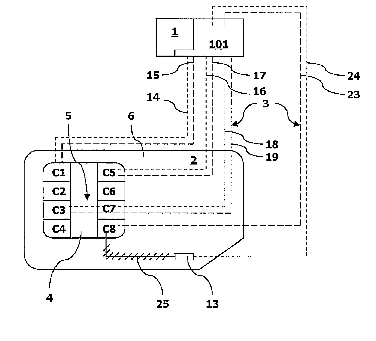
[0053] In a first embodiment, the allocation of the functions of the contacts C1-C8 is dynamic.

[0054] As already said, it is desired to have a more efficient use the contacts of the physical interface 3, in order for instance to raise the data transfer speed or add the implementation of an extra application and / or protocol.

[0055] To allow the implementation of multiple interface configurations without changing the current physical interface, FIG. 7 shows that the allocation of the functions of the contacts C1-C8 is done and changed dynamically.

[0056] In the first embodiment, the eight existing ISO contacts C1-C8 are allocated and reallocated dynamically within the interface 3 of the smart card 2, depending on the interface configuration which is needed for the use of a protocol, such as MMC, USB, contactless transfer application or any other protocol.

[0057] To this end, the device 1 comprises dynamic allocation means 100 and / or the smart card 2 comprises dynamic allocation means...

second embodiment

[0071] In a second embodiment, the allocation of the functions of the contacts C1-C8 or 13 is static. The static allocation is based on the use of a common contact for a common function in several protocols of data transfer through the interface 3. Some contacts are shared between different protocols and interfaces configurations.

[0072] As already said, it is desired to have a more efficient use of the contacts of the physical interface 3, in order for instance to raise the transfer speed or add the implementation of an extra application and / or protocol.

[0073] To allow the implementation of multiple interfaces configurations without changing too much the current physical interface, FIG. 8 shows that the allocation of the functions of the contacts C1-C8 is static. The principle is to reuse some of the ISO contacts in different interface configurations, whether the interface configuration is a MMC or any other.

[0074] In the second embodiment, the eight existing ISO contacts C1-C8 a...


PUM


Abstract

The invention relates to a method for a more efficient use of an interface between a smart card and a device, the interface comprising contacts and being adapted to allow data transfer between the smart card and the device characterized in that it comprises a step of allocating functions to the contacts within the interface so as to have a more efficient use of the contacts in the interface. The invention also relates to a smart card and a device in which the method is carried out.

Description

CROSS-REFERENCE TO RELATED APPLICATION [0001] Pursuant to 35 U.S.C. § 119(a), this application claims the benefit of earlier filing date and right of priority to European Patent Application No. 05292770.4, filed on Dec. 22, 2005, the contents of which are hereby incorporated by reference herein in their entirety. FIELD OF THE INVENTION [0002] The present invention relates to a method for a more efficient use of an interface between a smart card and a device, the interface comprising contacts and being adapted to allow data transfer between the smart card and the device. [0003] The invention also relates to a smart card and a device in which the method is carried out. BACKGROUND OF THE INVENTION [0004]FIG. 1 is a schematic representation of a known interface 3 between a smart card 2 and a device 1. [0005] In the present specification, the device 1 is preferably a telecommunication terminal, such as a mobile handset, but also can be any device, such as a personal computer. [0006] Simi...

Claims


Application Information

Patent Timeline
Patent Type & Authority Applications(United States)
IPC IPC(8): G06K7/06G06K19/06
CPCG06K7/0008G06K7/10297G06K19/07G06K19/07733
Inventor JOLIVET, PAUL
Owner LG ELECTRONICS INC
Why Eureka
Try Eureka