Rail grooming machine and method of use

a technology of rails and grooming machines, which is applied in the direction of railway tracks, milling equipment, large fixed members, etc., can solve the problems of increasing the number of operators in the operator's cab of the portal crane, accelerating metal fatigue, and prone to wear and roughness of the cross beams of the rails

Inactive Publication Date: 2007-06-28
FENTON DAVID S
View PDF15 Cites 9 Cited by
  • Summary
  • Abstract
  • Description
  • Claims
  • Application Information

AI Technical Summary

Benefits of technology

[0005] According to another aspect of the present invention there is provided a method, including a first step of providing an apparatus as described above. A second step involves securing the mounting body to a trolley which travels parallel to a rail requiring grooming ensuring that the primary pivot axis is positioned parallel to the rail. A third step involves positioning the rail grooming head on the rail. A fourth step involves moving the trolley parallel to the rail while maintaining the rail grooming head in working contact with the rail. The primary pivot axis accommodates limited vertical movement of the trolley relative to the rail.

Problems solved by technology

Rails on portal crane cross beams tend to wear and get rough after years of heavy loads being run on them.
This causes vibration, which accelerates metal fatigue.
It also creates an increasingly rough ride for an operator positioned in an operators cab of the portal crane.
These rails can be 300 feet long and are very expensive to replace, so a method of servicing them in place is required.
Similar problems relating to servicing rails have been encountered in other industries.

Method used


Image

  • Rail grooming machine and method of use
  • Rail grooming machine and method of use
  • Rail grooming machine and method of use

Examples


Embodiment Construction

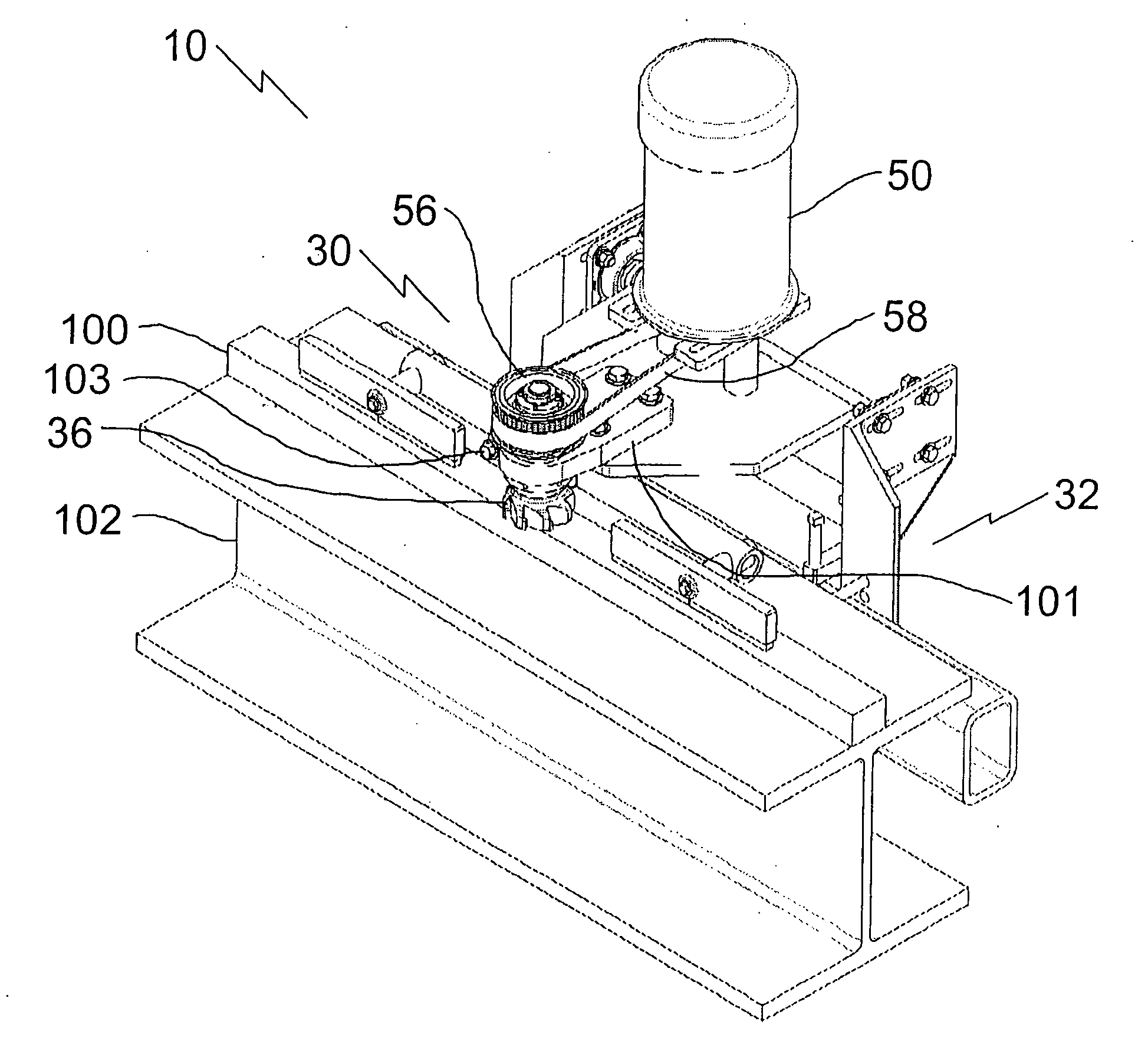
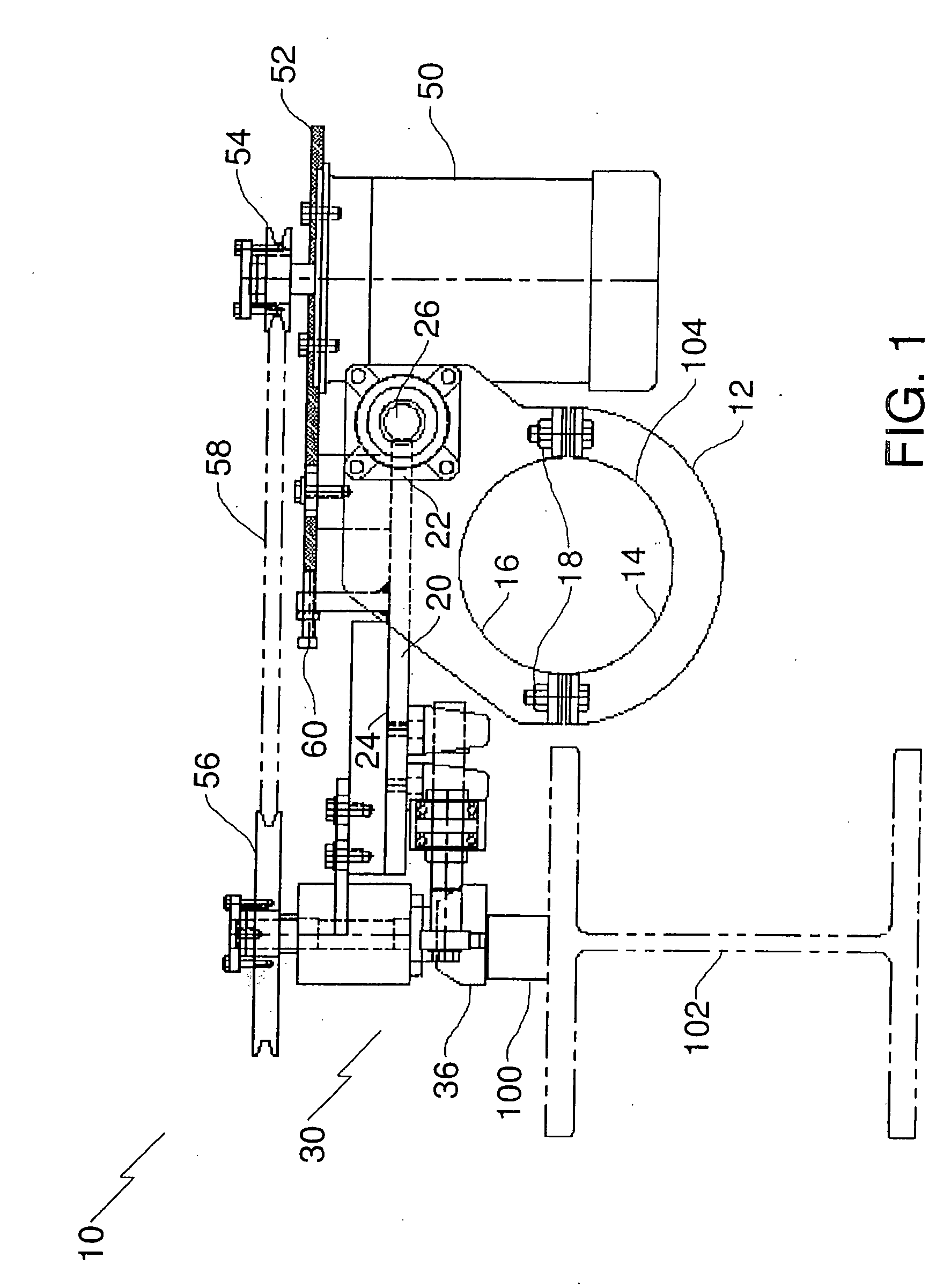
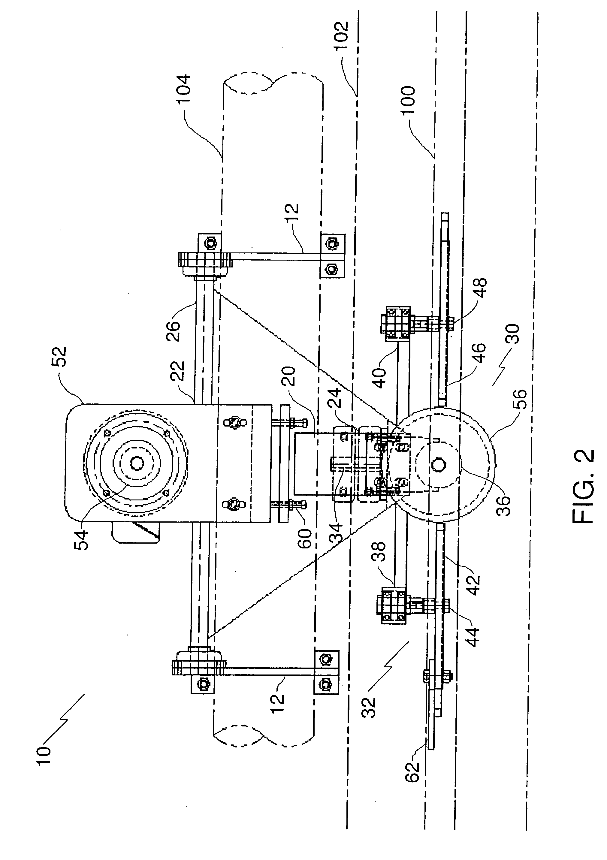
[0014] The preferred embodiment, a rail grooming machine generally identified by reference numeral 10, will now be described with reference to FIG. 1 through FIG. 3.

[0015] Structure and Relationship of Parts:

[0016] Referring to FIG. 1, rail grooming machine 10 has a mounting body generally indicated by reference numeral 12. Mounting body 12 consists of two clamping sections 14 and 16. As will hereinafter be further described in the description of operation, sections 14 and 16 are adapted to clamp around an object. Sections 14 and 16 are, preferably, maintained in this clamping relationship by fasteners 18, which in FIG. 1 are illustrated as being nuts and bolts. Referring to FIG. 1 and FIG. 2, a support 20 is provided having a first end 22 and a second end 24. First end 22 of support 20 is pivotally secured to mounting body 12 for pivotal movement about a substantially horizontal primary pivot axis, represented by shaft 26. A rail grooming head, generally indicated by reference nu...


PUM


Abstract

An apparatus having a mounting body, a support having a first end and a second end. The first end of the support being pivotally secured to the mounting body for pivotal movement about a substantially horizontal primary pivot axis. A rail grooming head mounted to the second end of the support.

Description

FIELD OF THE INVENTION [0001] The present invention relates to a rail grooming machine that was developed to service rails on a cross beam of a portal crane, and a method of use of the same. BACKGROUND OF THE INVENTION [0002] Rails on portal crane cross beams tend to wear and get rough after years of heavy loads being run on them. This causes vibration, which accelerates metal fatigue. It also creates an increasingly rough ride for an operator positioned in an operators cab of the portal crane. These rails can be 300 feet long and are very expensive to replace, so a method of servicing them in place is required. [0003] Similar problems relating to servicing rails have been encountered in other industries. Examples of solutions proposed in the prior art include: U.S. Pat. No. 4,135,332 (Theurer 1979) entitled “Rail Grinding Machine”; U.S. Pat. No. 5,575,709 (Hertelendi et al 1996) entitled “Rail Grinding Machine For Grinding Rails Of A Track”; U.S. Pat. No. 5,735,734 (Hertelendi 1998...

Claims


Application Information

Patent Timeline
Patent Type & Authority Applications(United States)
IPC IPC(8): B23C1/20
CPCE01B31/17Y10T409/3042Y10T409/3084Y10T409/306384Y10T409/308624Y10T409/501312Y10T409/50164Y10T409/307672Y10T409/303808Y10T409/306496B23C3/005E01B31/13
Inventor FENTON, DAVID S.
Owner FENTON DAVID S
Why Eureka
Try Eureka