Ring shaped spring device

a spring device and ring technology, applied in the direction of mechanical actuating clutches, wound springs, shock absorbers, etc., can solve the problems of unbalance, damage and/or unintended biasing forces, and the force produced by the orlowski spring device is not maximized, so as to achieve the effect of maximizing the for

Inactive Publication Date: 2004-10-28
BARNES GROUP
View PDF21 Cites 10 Cited by
  • Summary
  • Abstract
  • Description
  • Claims
  • Application Information

AI Technical Summary

Benefits of technology

[0004] The present invention relates to a ring-shaped spring device as shown in Orlowski wherein there are a plurality of locking assemblies located at circumferentially spaced positions around the ring that are each within one of the coil spring's center passage. In this respect each of these lock assemblies includes a first element extending from one of the plates toward the other plate, a second element extending in the opposite direction from the other plate to form a generally sliding contact between the first and second elements as the spaced plates move vertically to compress and release the coil springs. The first and second elements are sized and shaped to fit within the center passage of the coil spring. This configuration maximizes the force produced by the ring shaped spring device and balances the circumferentially extending spring action.
[0005] In accordance with another aspect of the present invention, the first and second elements or tabs include a guiding mechanism to restrict annular movement at the plates relative to one another. The first tab having a guide slot with a given width and which extends in a direction perpendicular to the plates. The second tab having a hook shaped guide member which extends through the guide slot to restrict the vertical movement between the two plates. The width of the hook corresponds with the width of the slot which provides the guiding mechanism between the two plates. The structure assembly procedure and operation of the present invention is different than the ring shaped spring device in Orlowski. These added features further result in the advantage of being capable of maintaining the proper annular orientation between the spaced plates during long term operation of the spring device in an automatic transmission.

Problems solved by technology

However, when assembled in a transmission, the ring shaped spring device is compressed further so that the hook actually disengages the loop.
Consequently, during repetitive operation of the spring assembly over many years, the individual coil springs can become canted in a manner to reduce the spring constant and cause damage and / or unintended biasing forces.
Consequently, the prior ring shaped spring device, as shown in Orlowski only employs the concept of integral interconnecting elements and does not address the problem of controlling the annular movement of the spaced plates during long term operation of the spring device.
As a result, the force produced by the Orlowski spring device is not maximized and is not balanced.

Method used


Image

  • Ring shaped spring device
  • Ring shaped spring device
  • Ring shaped spring device

Examples


Embodiment Construction

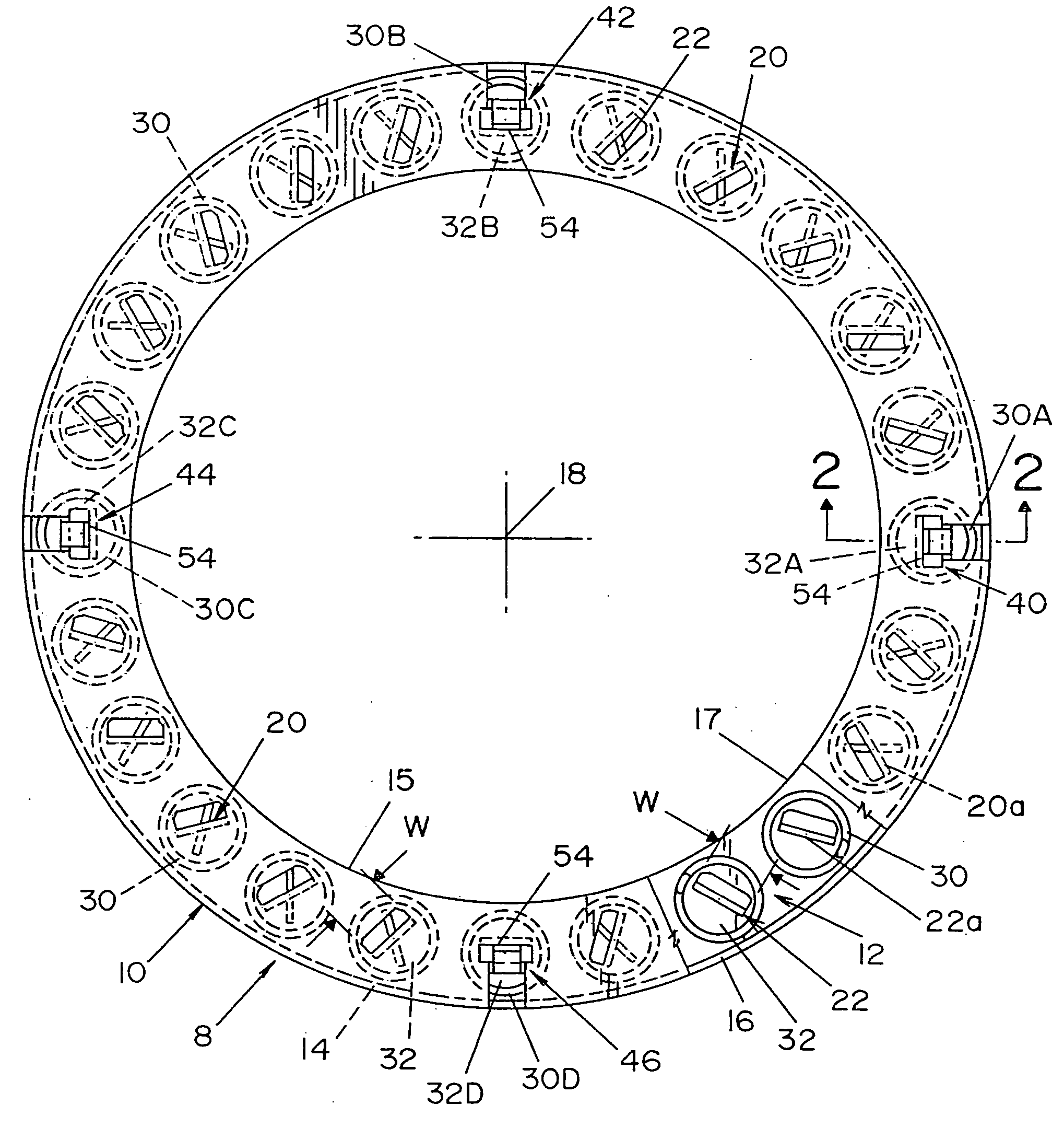
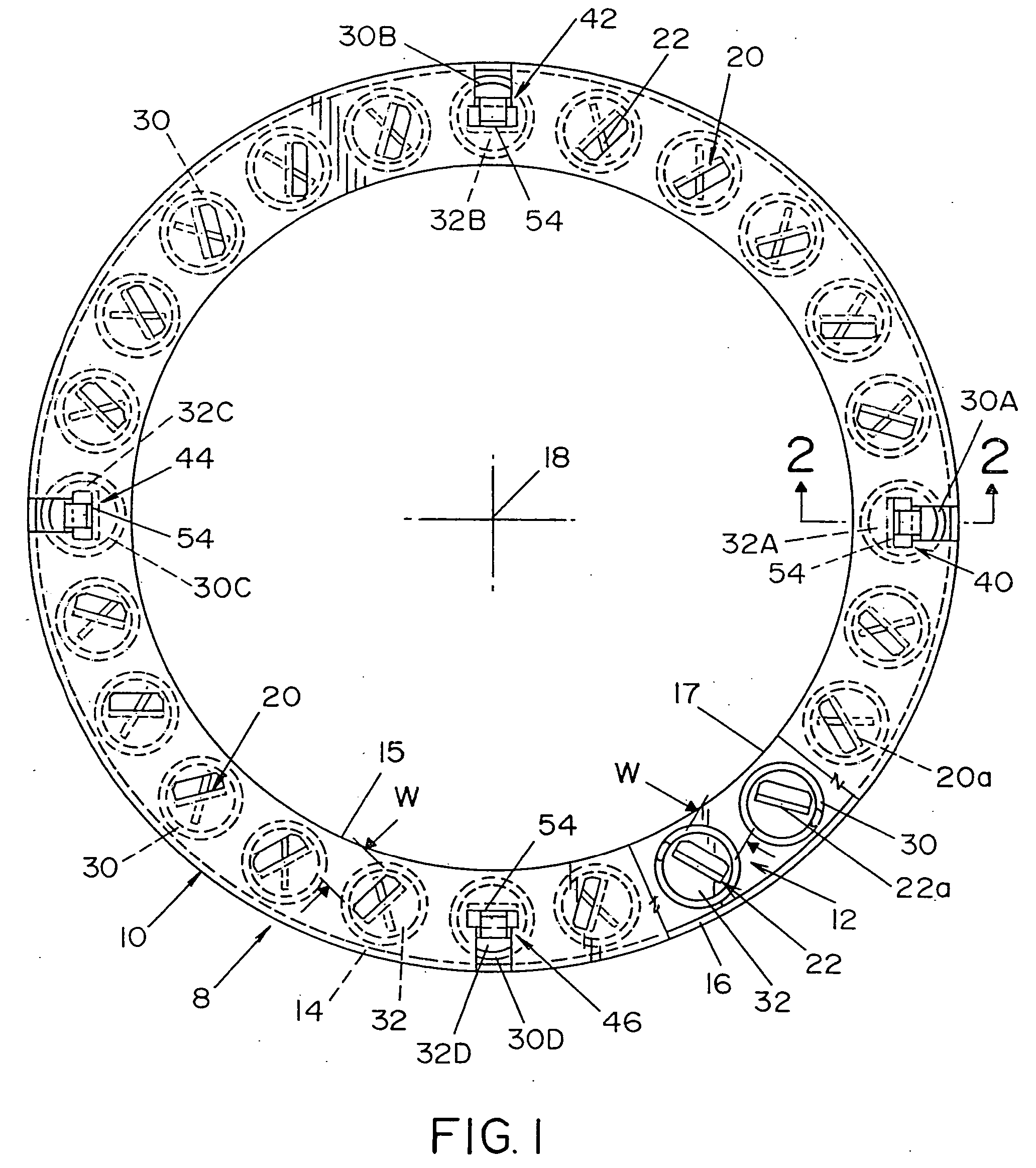
[0043] Referring now to the drawings, wherein the showings are for the purpose of illustrating preferred embodiments of the invention only and not for the purpose of limiting same, FIGS. 1, 2, 3 and 4 show a ring shaped spring device 8 having annular spaced-apart plates 10, 12 with outer rims 14, 16, respectively, and inner edges 15, 17. Plates 10, 12 are coaxial to axis 18 and include spring tabs 20 of plate 10 and spring tabs 22 of plate 12. The tabs, sometimes called "elements", are lanced from a center portion of its respective plate and are bent to locate at circumferentially spaced positions a number of coil springs 30. The spring tabs 20, 22 have spaced distal edges 20a, 22a facing one another and have a length such that there is a gap between edges 20a, 22a when device 8 as a whole is in a free state. Edges 20a, 22a engage one another to limit the vertical movement of plates 10, 12 toward one another. The widths W of the spring tabs are just slightly smaller than the diamete...


PUM


Abstract

A spring device comprising at least one annular support plate defining a ring with a central axis; a plurality of circumferentially spaced, parallel oriented coil springs disposed about the at least one annular plate; and, a plurality of lock assemblies spaced about the plate. Each of the lock assemblies being in position within a spring cavity of one of the coil springs to allow additional springs to be provided on the spring device. In addition, the lock assemblies are dimensioned so that the coil spring is retained in a prestressed condition.

Description

[0001] The present invention relates to a spring device and more particularly to a spring device of the type used in automatic transmissions for motor vehicles.INCORPORATION BY REFERENCE[0002] Automatic transmissions for vehicles often include a plurality of coil springs that are adapted to apply a biasing force against clutch plates that control the engagement of various gears in the transmission. These coil springs are assembled in a ring shaped device comprising two annular plates having a multiplicity of circumferentially spaced, parallel compression coil springs mounted therebetween. Such a ring shaped spring device is disclosed in Orlowski U.S. Pat. No. 5,306,086, which is incorporated by reference herein as the basic background to which the present invention is directed. A ring shaped spring device is also disclosed in pending application Ser. No. 10 / 078,465 filed on Feb. 2, 2002 which is incorporated by reference herein as the basic background to which the present invention ...

Claims


Application Information

Patent Timeline
Patent Type & Authority Applications(United States)
IPC IPC(8): F16B21/07F16F1/12F16F3/04
CPCF16B21/071F16B21/073F16F1/128F16F3/04
Inventor COSTELLO, PHILIP G.HROVAT, FRANK R.
Owner BARNES GROUP
Why Eureka
Try Eureka