Long stroke linear solenoid

a technology of linear solenoid and long stroke, which is applied in the direction of magnetically actuated clutches, magnets, magnetic bodies, etc., can solve the problems of insufficient short stroke solenoid and difficult design of longer stroke solenoid, and achieve the effect of maximizing for

Inactive Publication Date: 2019-09-24
GM GLOBAL TECH OPERATIONS LLC
View PDF28 Cites 6 Cited by
  • Summary
  • Abstract
  • Description
  • Claims
  • Application Information

AI Technical Summary

Benefits of technology

[0005]A long-stroke linear solenoid assembly is provided having a pole shape that includes a plurality of angled steps. The specific design of the pole (plunger) pieces, as well as the yoke and windings, maximizes force for a long distance stroke, such as for example, a two or four millimeter stroke.

Problems solved by technology

However, in an application where the solenoid travel distance along the stroke may need to change over time, such as due to components wearing or eroding, a short-stroke solenoid may be insufficient.
Longer stroke solenoids, however, are much more difficult to design because they need to have sufficient force to provide actuation and deactuation along a large travel path.

Method used


Image

  • Long stroke linear solenoid
  • Long stroke linear solenoid
  • Long stroke linear solenoid

Examples


Embodiment Construction

[0018]The following description is merely exemplary in nature and is not intended to limit the present disclosure, its application, or its uses.

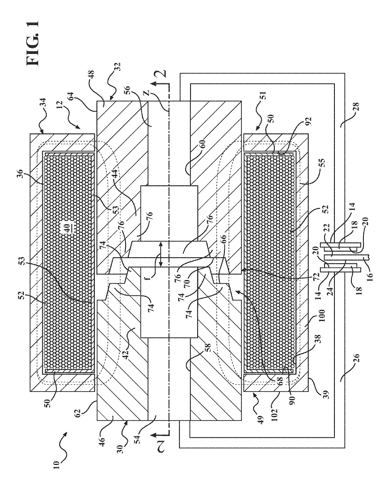
[0019]With reference to FIG. 1, a clutch assembly for use in a transmission (not shown) of a motor vehicle (not shown) is illustrated and generally indicated by reference number 10. The clutch assembly 10 is actuated by a solenoid assembly 12. The clutch assembly 10 is merely one non-limiting example of an application for the solenoid assembly 12, and it should be understood that the solenoid assembly 12 has use in various different applications, as well.

[0020]The clutch assembly 10, in this example, includes a pair of engaging members, such as apply plates 14 that are selectively engageable with an independent member, such as a reaction plate 16. A force may be applied to the apply plates 14 to bring the apply plates closer to each other and squeeze the apply plates 14 against the reaction plate 16. When the apply plates 14 are engaged with...


PUM

PropertyMeasurementUnit
angleaaaaaaaaaa
angleaaaaaaaaaa
travel distanceaaaaaaaaaa

Abstract

A solenoid assembly is provided that includes male and female plungers and an electromagnetic coil configured to be energized to create a magnetic flux. Each plunger has a plunger face, where the female plunger face is configured to correspond with the male plunger face. The male plunger has a plurality of angled plunger steps that define the male plunger face, each angled plunger step including a corner having an angle in the range of 95 degrees to 115 degrees. The female plunger face has a similar, corresponding angled face. The solenoid assembly is suitable for use as a long stroke linear solenoid.

Description

FIELD[0001]This disclosure relates generally to a solenoid assembly, and more particularly to a solenoid assembly capable of long-stroke force generation.INTRODUCTION[0002]Typical stepped or continuously variable transmissions employ a hydraulic control system operable to perform various functions within the transmission. These functions include actuating torque transmitting devices such as drive / reverse clutches or torque converter clutches, setting belt pulley positions, transmission cooling, and lubricating the components of the transmission. Valves and solenoids are configured to actuate the clutches and brakes. Fluid passages are formed within the valve body and connect the pump to the valves and solenoids which selectively control the supply of pressurized hydraulic fluid to the various components of the transmission. Short-stroke solenoids are typically sufficient for controlling hydraulic fluid actuation.[0003]Other devices that use solenoid control are fuel injectors and / or...

Claims


Application Information

Patent Timeline
Patent Type & Authority Patents(United States)
IPC IPC(8): F16D27/112H01F7/16
CPCF16D27/112H01F7/1653H01F7/081H01F7/1607H01F2007/086F16D2027/008
Inventor FATEMI, ALIREZANEHL, THOMAS WNAMUDURI, CHANDRA S
Owner GM GLOBAL TECH OPERATIONS LLC
Why Eureka
Try Eureka