Flag block for a document feeding system

a document feeding and flag block technology, applied in the direction of transportation and packaging, thin material processing, article separation, etc., can solve the problems of detectors, large hopper capacity, and difficulty in consistent presentation, and achieve the effect of reducing the cos

Inactive Publication Date: 2007-08-21
BURROUGHS CORP
View PDF15 Cites 6 Cited by
  • Summary
  • Abstract
  • Description
  • Claims
  • Application Information

AI Technical Summary

Benefits of technology

[0015]It is, therefore, an object of the invention to provide an improved system for feeding and transporting documents that is able to process envelope stacks with improved performance by utilizing an improvement to the flag in the form of a flag block. In a preferred approach to providing the flag block, it is possible to quickly convert a standard sorter to cope with stacks of envelopes with minimal alteration, and to allow reversion to standard configuration.
[0017]According to the invention, a flag block is used to improve performance when feeding envelopes. The flag block can be attached to the existing flag when a need arises to feed envelopes. It also would be possible, for certain applications, to form the flag block integrally as part of the standard flag configuration. In either approach, the flag block comprises a horizontal element for concentrating the flag force in the desired position on the nudger belt or equivalent structure. This horizontal element is shaped so that it essentially does not apply any force anywhere else such that the envelope stack may expand freely. In this way, it is possible to maximize the nudging force, minimize the drag force, and generally cause the feeder to behave as though it is feeding single thickness items.
[0018]Put another way, the flag block horizontal element has considerable depth in order to cope with the spongy nature of the envelope stack. Force can thus be concentrated on the nudger belt as desired, while it is possible to eliminate force against stationary features. That is, the horizontal element has depth away from the feeder. Thus, the documents are essentially free to expand for the purpose of improving feeder behavior.
[0020]According to another preferred feature, the face of the horizontal element which meets the nudger belt is concave. The purpose of this feature is to column form the last document in a stack. This stiffens the column formed document in the direction of travel, making it easier to feed. Envelopes are relatively heavy, and feed better with higher feeding forces. Light documents, such as intermixed stubs, would perform better with lighter feeding forces. When the ability to adjust feeding force is unavailable, by column forming light items, these items may be fed successfully at higher feeding forces. Put another way, the concave face of the horizontal element has an axis parallel to the direction of feeding. This concavity column forms the last few documents in the stack, and provides better feeding for light documents which may be intermixed with the envelopes.
[0022]The invention provides numerous advantages for a document feeding system. In a preferred approach, a machine may be convertible to multiple tasks by the operator, at minimum cost, without a service call.

Problems solved by technology

The difficulty with making hopper capacity larger is one of consistency.
The variety of documents used in different applications make such consistent presentation difficult.
Considerable effort (for example, double document detectors) goes into ensuring that only one thickness of paper is fed at a time.
However, envelope stacks (for example, a stack of ATM envelopes) are spongy.
Accordingly, envelope stacks are only processed with limited performance due to the fact that document processing systems are normally built to handle single thickness items.

Method used


Image

  • Flag block for a document feeding system
  • Flag block for a document feeding system
  • Flag block for a document feeding system

Examples


Embodiment Construction

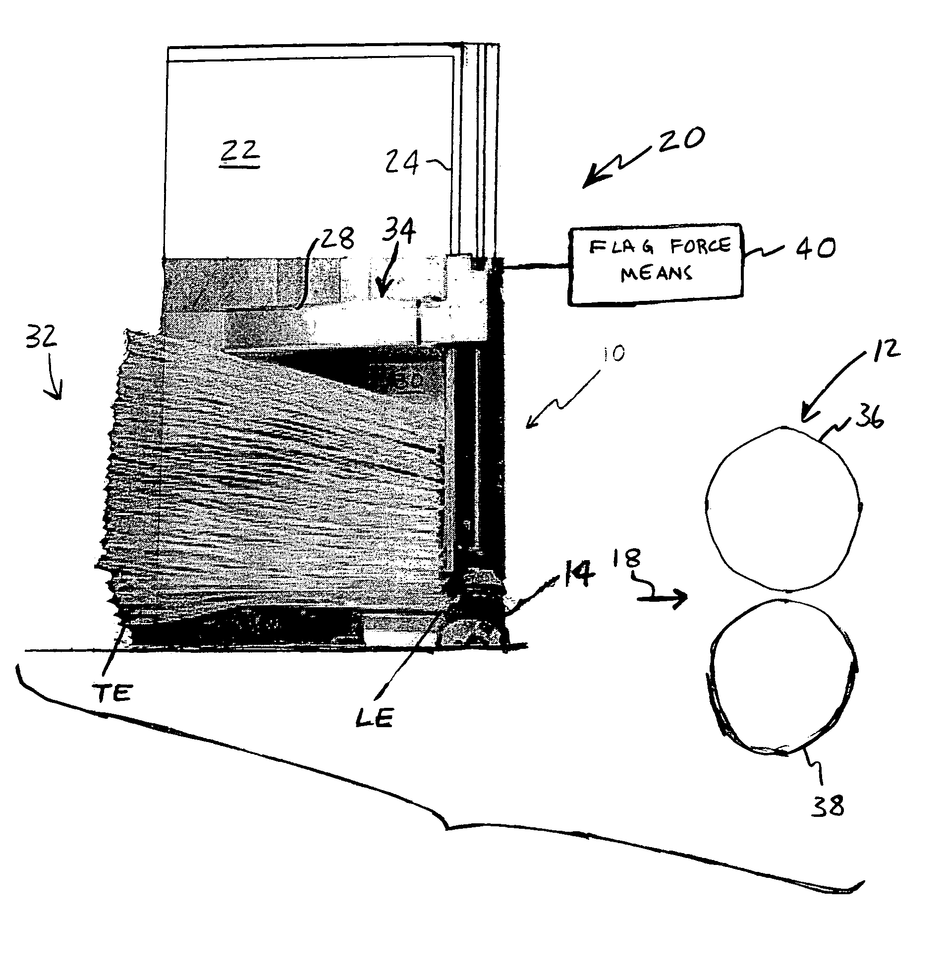
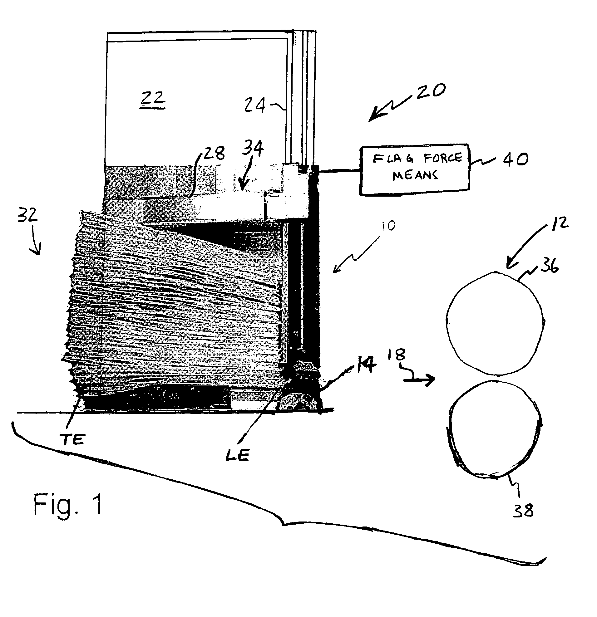
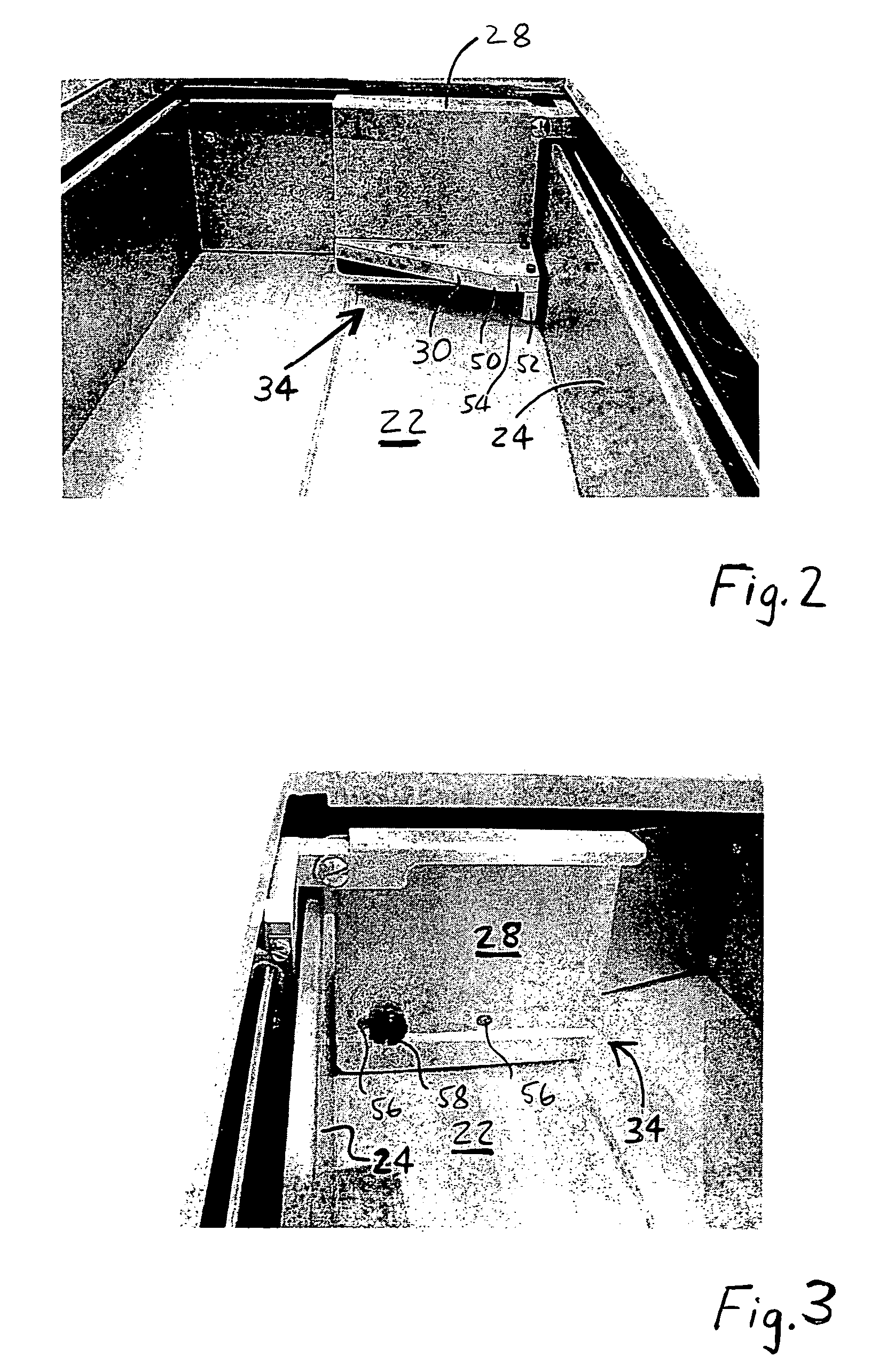
[0026]FIG. 1 illustrates a system for feeding and transporting documents. The system includes a feeder stage 10 and a transport stage 12. The feeder stage 10 includes a feeder including nudger belt 14. Transport stage 12 is downstream of feeder stage 10, with arrow 18 pointing in the downstream direction. A document leading edge LE is the more downstream edge, while the trailing edge TE is the more upstream edge. Feeder stage 10 includes hopper assembly 20. Hopper assembly 20 includes a hopper floor 22 and hopper sidewall 24. Hopper assembly 20 further includes document stack supporter or flag 28. Flag block 30 is attached to flag 28. A stack 32 of documents, the documents being envelopes, engages hopper floor 22, flag 28 and flag block 30.

[0027]With continuing reference to FIG. 1, envelope stack 32 is shown adjacent to hopper sidewall 24. The components shown in FIG. 1 are exemplary and alternative arrangements are possible as known to those skilled in the art. For example, the fee...


PUM


Abstract

A system for feeding and transporting documents includes a feeder stage and a transport stage. Documents are fed singly, in order, from a stack of documents in a hopper assembly. A flag / flag block arrangement provides a force to move the documents along the hopper floor toward the feeder and to feed a document with a presentation force. The flag block includes a horizontal element for concentrating the presentation force at a desired position at the feeder. The horizontal element has sufficient depth away from the feeder such that the documents are essentially free to expand, thereby concentrating the presentation force while reducing drag forces. The flag / flag block arrangement is useful, for example, when the system is used to process envelopes.

Description

BACKGROUND OF THE INVENTION[0001]1. Field of the Invention[0002]The invention relates to systems for feeding and transporting documents, to document hoppers used in these systems, and to adapting these systems for feeding envelopes and the like.[0003]2. Background Art[0004]A typical system for feeding and transporting documents includes a feeder in the document feeding portion of the system, and a series of roller pairs or belts in the document transporting portion of the system. In the feeding portion of the system, the feeder acts to separate and feed documents singly, in order, from a stack. In the transporting portion of the system, the roller pairs and / or belts convey the documents, one at a time, past other processing devices such as readers, printers, and sorters that perform operations on the documents. The feeder is typically a feed wheel, but may take other forms. Further, the components in the transporting portion of the system may take a variety of forms. An existing doc...

Claims


Application Information

Patent Timeline
Patent Type & Authority Patents(United States)
IPC IPC(8): B65H1/02
CPCB65H1/02B65H1/025B65H2701/1916
Inventor SPALL, J. MICHAEL
Owner BURROUGHS CORP
Why Eureka
Try Eureka