Thermal management system for a removable build chamber for use with a laser sintering system

a technology of thermal management system and build chamber, which is applied in the direction of additive manufacturing process, electric/magnetic/electromagnetic heating, manufacturing tools, etc., can solve the problems of inactive sintering apparatus, inability to build subsequently, and lateral misalignment of successive fused layers of powder,

Active Publication Date: 2010-09-07
3D SYST INC
View PDF13 Cites 51 Cited by
  • Summary
  • Abstract
  • Description
  • Claims
  • Application Information

AI Technical Summary

Benefits of technology

[0017]It is another advantage of the present invention that a controlled cool down of the removed build chamber with the newly built part and the surrounding unfused powder forming the part cake is obtained so that thermal distortion does not occur in the newly built part.
[0018]These and other aspects, features and advantages are obtained by use of a thermal management station that controls the cool down of the removed build chamber with the part cake inside and the preheating of the replacement build chamber to permit quick changeover of a laser sintering system between a completed part build and the start of a new build.BRIEF DESCRIPTION OF THE SEVERAL VIEWS OF THE DRAWING(S)

Problems solved by technology

As a result, the laser sintering apparatus may be inactive during the cooling time, which may cause the apparatus to be unavailable for subsequent builds.
Incorrect alignment of the powder spreader and the vertical travel of the build platform may result in the depositing of non-uniform powder layers and / or lateral misalignment on successive fused layers of powder.
Building a part on an incorrectly aligned build platform may result in a defective part that may be unusable.
The alignment process may result in lost time and inefficiencies in the RP&M process.
Physically lifting the container may be undesirable because the container is heavy and the lifting process could cause the part to shift, resulting in damage to the part.
An additional problem is the delay incurred when using a removable container or build chamber with a laser sintering apparatus waiting for the build chamber to be heated up to the operating temperature after the removable component is inserted into the laser sintering apparatus.

Method used


Image

  • Thermal management system for a removable build chamber for use with a laser sintering system
  • Thermal management system for a removable build chamber for use with a laser sintering system
  • Thermal management system for a removable build chamber for use with a laser sintering system

Examples


Embodiment Construction

[0023]The present invention now will be described more fully hereinafter with reference to the accompanying drawings in which some, but not all, embodiments of the invention are shown. Indeed, the invention may be embodied in many different forms and should not be construed as limited to the embodiments set forth herein; rather, these embodiments are provided so that this disclosure will satisfy applicable legal requirements. Like numbers refer to like elements throughout.

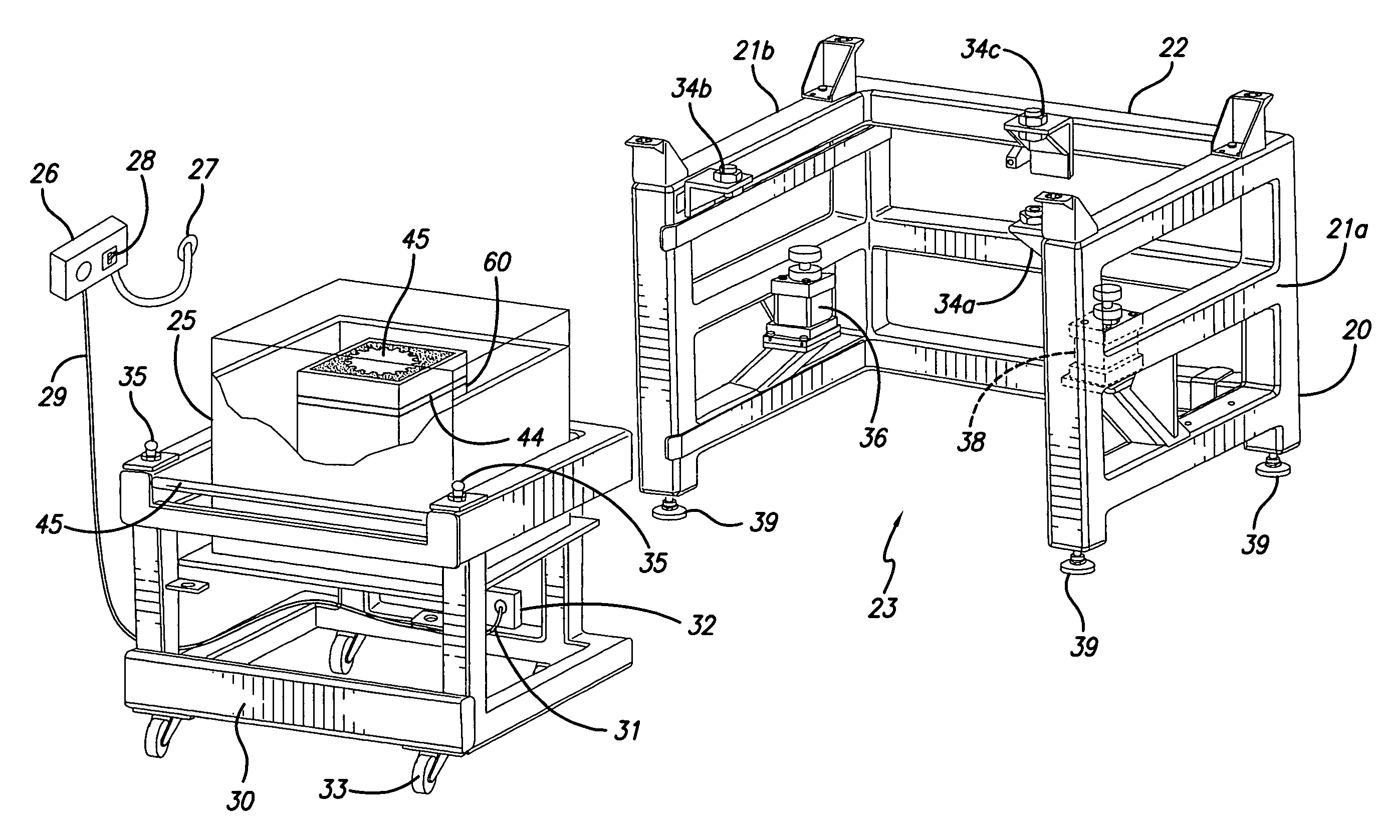
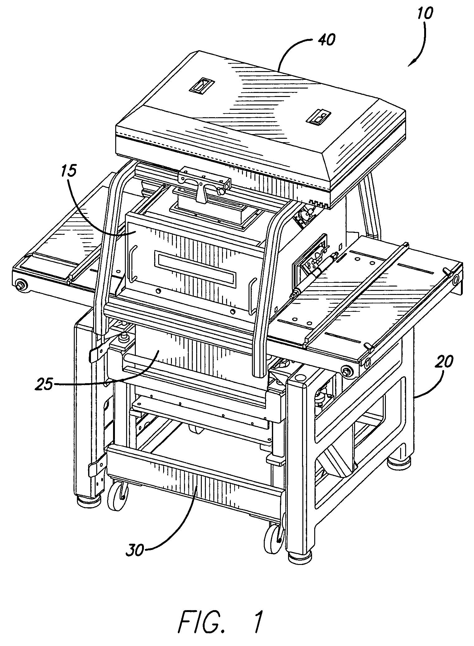
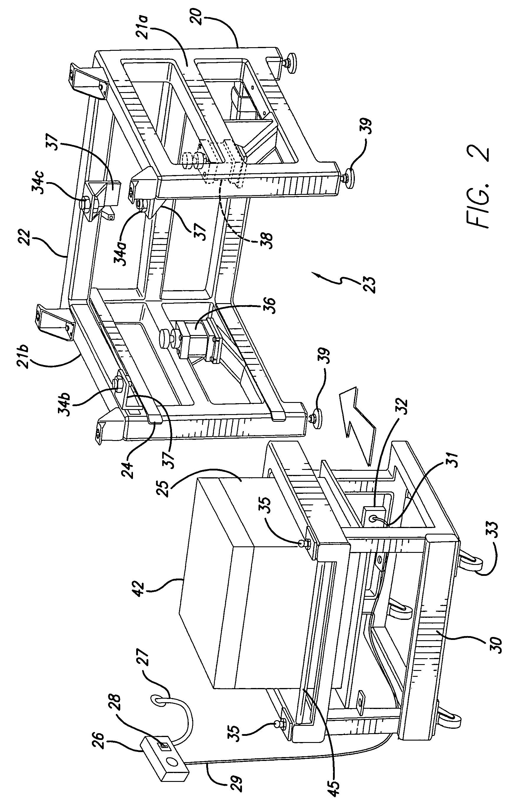
[0024]With reference to FIG. 1, a laser sintering apparatus or system having a removable build chamber is illustrated and broadly designated as reference number 10. The laser sintering system 10 includes a process chamber 15, an associated support housing 20, and a removable build chamber 25 that may be supported by a build carriage 30. The build carriage 30, along with the build chamber 25, may be removably inserted into the support housing 20. In some embodiments, the laser sintering apparatus 10 may include a li...


PUM

PropertyMeasurementUnit
temperatureaaaaaaaaaa

Abstract

A thermal management system is provided to control the preheating and cool down of a removable build chamber in a laser sintering system. A thermal management station controls preheating of a removable build chamber to heat the chamber to a temperature at or near the operating temperature of the laser sintering system. After insertion into the laser sintering system and completion of a build the thermal management station controls the cool down of the part cake within the removable build chamber after the chamber has been removed from the laser sintering system.

Description

BACKGROUND OF THE INVENTION[0001]The invention relates generally to a method of rapid prototyping and manufacturing and, more particularly, to laser sintering and the ability to more quickly turn around a laser sintering system after completion of a first part build to commence a subsequent build.[0002]Rapid prototyping and manufacturing (RP&M) is the name given to a field of technologies that can be used to form three-dimensional objects rapidly and automatically from computer data representing the objects. In general, rapid prototyping and manufacturing techniques build three-dimensional objects, layer-by-layer, from a working medium utilizing sliced data sets representing cross-sections of the object to be formed. Typically an object representation is initially provided by a Computer Aided Design (CAD) system. RP&M techniques are sometimes referred to as solid imaging and include stereolithography, ink jet printing as applied to solid imaging, and laser sintering.[0003]A laser si...

Claims


Application Information

Patent Timeline
Patent Type & Authority Patents(United States)
IPC IPC(8): B27N5/00B29C41/02B29C35/08B29C41/52
CPCB29B13/021B29C67/0077B29C35/16B29C2037/90B29C64/153B33Y40/00B33Y40/10B33Y40/20
Inventor MEROT, CHRISTIAN M.CHUNG, TAE MARKBISHOP, RAYMOND J.
Owner 3D SYST INC
Why Eureka
Try Eureka