
Quick conversion connection system for a component of a vehicle-mounted equipment carrier

a technology of quick conversion and connection system, which is applied in the direction of screws, threaded fasteners, transportation and packaging, etc., can solve the problems of inconvenient and time-consuming operation, and achieve the effect of quick and easy movemen

Inactive Publication Date: 2006-06-06
SARIS CYCLING GROUP
View PDF11 Cites 50 Cited by
  • Summary
  • Abstract
  • Description
  • Claims
  • Application Information

AI Technical Summary

Benefits of technology

[0001]This invention relates to a vehicle-mounted equipment carrier, such as a bicycle rack, and more particularly to a system for providing quick and easy movement of a component of an equipment carrier between an operative position and an inoperative position.
[0003]It is an object of the present invention to provide an engagement system for a movable component of a vehicle-mounted equipment carrier, which enables the component to be quickly and easily moved between an operative position and an inoperative position, and then engaged in the desired position. It is a further object of the invention to provide such an engagement system which operates in a manner similar to the prior art, yet eliminates the need to make a large number of rotations of an engagement member so as to move the engagement member between an engaged position and a release position. It is a further object of the invention to provide such an engagement system which is easy to use and provides the ability to rapidly convert an equipment carrier from a storage configuration to a use configuration. A still further object of the invention is to provide such an engagement system which is relatively simple in its components and construction, yet which provides positive and secure engagement of the support member in either the operative or inoperative position.

Problems solved by technology

The user must repeatedly rotate the knob in order to back the knob away from the transverse member so as to provide sufficient clearance to enable movement of the support member, which is an inconvenient and time consuming operation.

Method used


Image

  • Quick conversion connection system for a component of a vehicle-mounted equipment carrier
  • Quick conversion connection system for a component of a vehicle-mounted equipment carrier
  • Quick conversion connection system for a component of a vehicle-mounted equipment carrier

Examples


Embodiment Construction

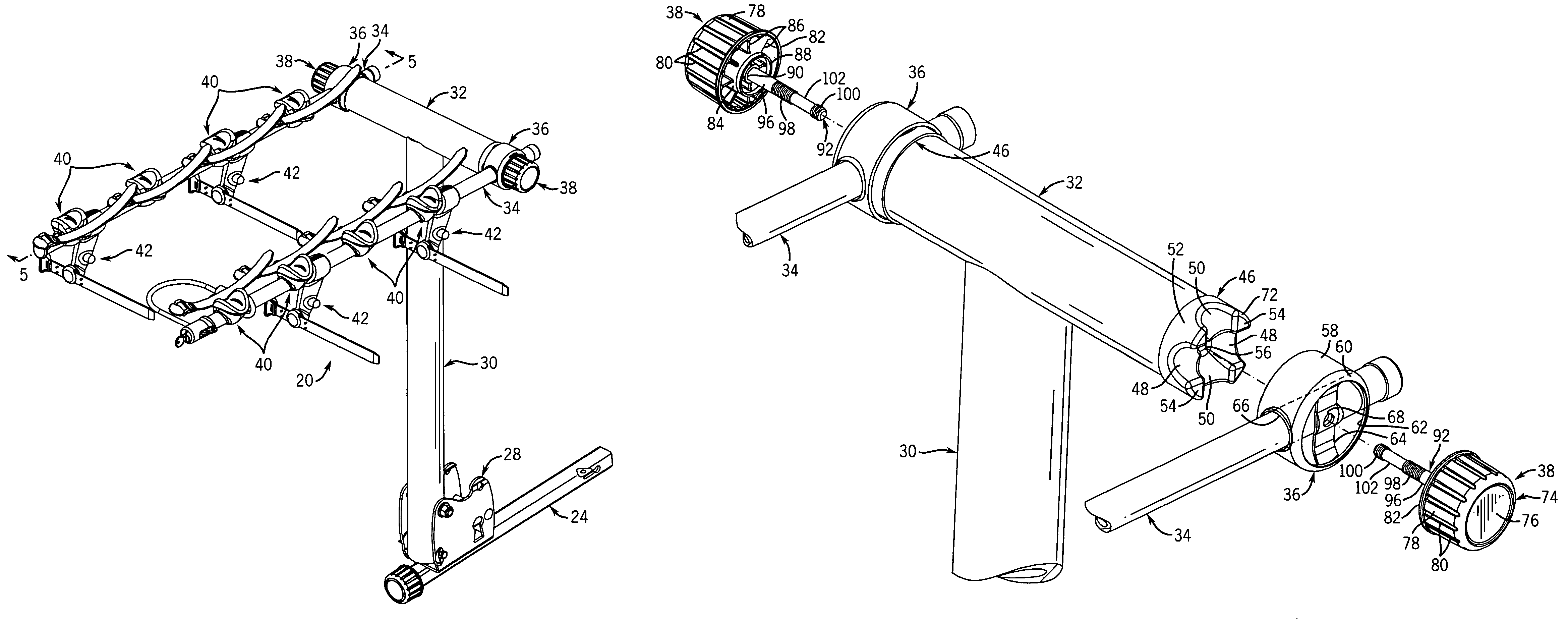
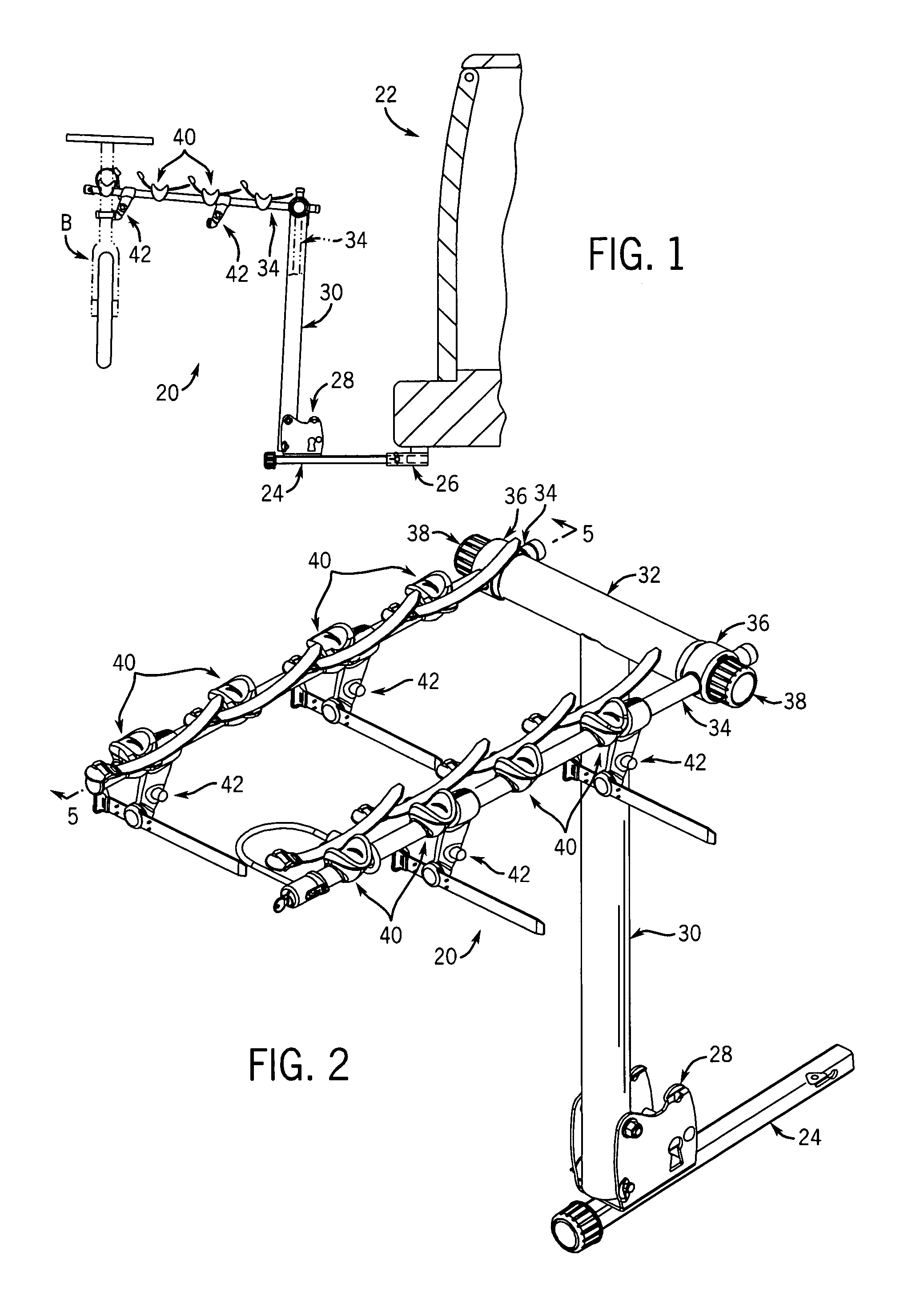
[0022]FIG. 1 illustrates an equipment carrier, in the form of a bicycle rack 20, secured to a vehicle 22 for supporting equipment, such as one or more bicycles B, on vehicle 22. Bicycle rack 20 is secured to vehicle 22 by engagement of a mounting member 24, which forms a part of bicycle rack 20, within a passage defined by a hitch receiver 26 that is mounted to vehicle 22 in a conventional manner. The connection of mounting member 24 to hitch receiver 26 is detailed in copending application Ser. No. 10 / 679,739 filed Oct. 06, 2003, the disclosure of which is hereby incorporated by reference.

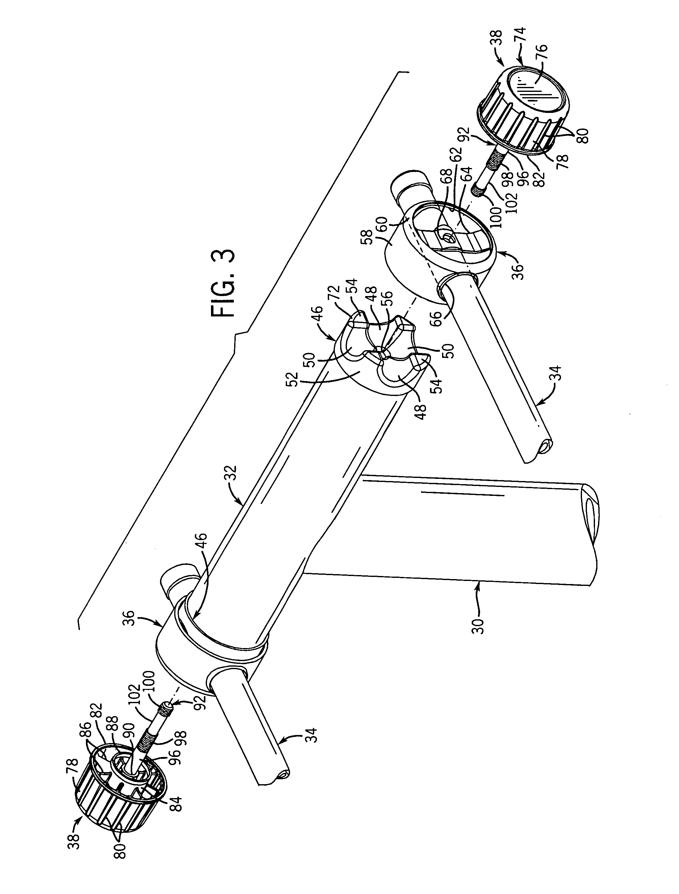
[0023]In the illustrated embodiment, bicycle rack 20 includes a mounting bracket 28 secured to mounting member 24, and an upwardly extending vertical support member 30 is connected at its lower end to mounting bracket 28. A transversely extending upper member 32 (FIG. 2) is secured to the upper end of vertical support member 30, and a pair of support arms 34 extend rearwardly from the ends of tran...


PUM


Abstract

A vehicle-mounted equipment carrier includes a base having a support member that is movable between an operative position and an inoperative position. An engagement member maintains the position of the support member, and is movable between an engaged position and a release position. The engagement member is movable between the engaged position and an intermediate position by a threaded connection with the base, is movable between the intermediate position and the release position by a sliding connection with the base. The shaft includes a threaded section that engages a threaded opening in the base, for providing movement of the engagement member between the engaged position and the intermediate position upon rotation of the engagement member, and an unthreaded section that moves the shaft axially within the opening for moving the engagement member between the intermediate position and the release position.

Description

BACKGROUND AND SUMMARY OF THE INVENTION[0001]This invention relates to a vehicle-mounted equipment carrier, such as a bicycle rack, and more particularly to a system for providing quick and easy movement of a component of an equipment carrier between an operative position and an inoperative position.[0002]A vehicle-mounted equipment carrier, such as a bicycle rack, typically includes a base that is mounted to the vehicle and a support component that is mounted to the base and is configured to support the item of equipment. The support component is typically in the form of a support member or arm that is movable between a raised, operative position for supporting the item of equipment, and a lowered, inoperative position for storage or when the carrier is mounted to the vehicle but not in use. In a common configuration, a support arm of the equipment carrier is pivotably mounted to a transverse member of the carrier, for movement between the raised, operative position and the lowered...

Claims


Application Information

Patent Timeline
IPC IPC(8): B60R9/06
CPCB60R9/06B60R9/10Y10S224/924
Inventor KOLDA, CLINT D.
Owner SARIS CYCLING GROUP
Learn More