Bicycle pedaling power unit with leverage shifting

a pedaling power unit and pedal technology, applied in the field of bicycles, can solve the problems of ineffective user power at the top of the cycle, insufficient methods, and high cost, and achieve the effects of maximum muscle power, continuous and sustained power, and maximum for

Inactive Publication Date: 2002-03-28
THIR PETER
View PDF0 Cites 7 Cited by
  • Summary
  • Abstract
  • Description
  • Claims
  • Application Information

AI Technical Summary

Benefits of technology

[0012] It is an object of the invention to position the driver of the bicycle with the body in a low position so that his legs can exert pedal movements with maximum muscle power.
[0013] Another object is to provide bicycle drive designs that can maximize the force that the body can exert on the pedals and wheels of the bicycle.
[0014] Another object is to provide bicycle drive designs where the user can exert a continuous and sustained level of power throughout the entire power stroke.
[0015] Another object is to provide bicycle drive designs where the travel of the wheel is maximized with the least amount of body motion.

Problems solved by technology

However, such methods are inadequate when compared with the amount of force that can be generated by the legs when a person is in the horizontal sitting position and braces his back against a strong support and uses his legs to exert pressure in the horizontal direction.
Such gain is likely to be in the neighborhood of several hundred pounds of torque.
This results in only a very narrow window in which the user can exert the most power from his legs.
In such case, the user's power is very ineffective at the top of the cycle, i.e. with the pedal at the top or at 0.degree. (180.degree. being when the pedal is at the bottom of the cycle).

Method used


Image

  • Bicycle pedaling power unit with leverage shifting
  • Bicycle pedaling power unit with leverage shifting
  • Bicycle pedaling power unit with leverage shifting

Examples


Embodiment Construction

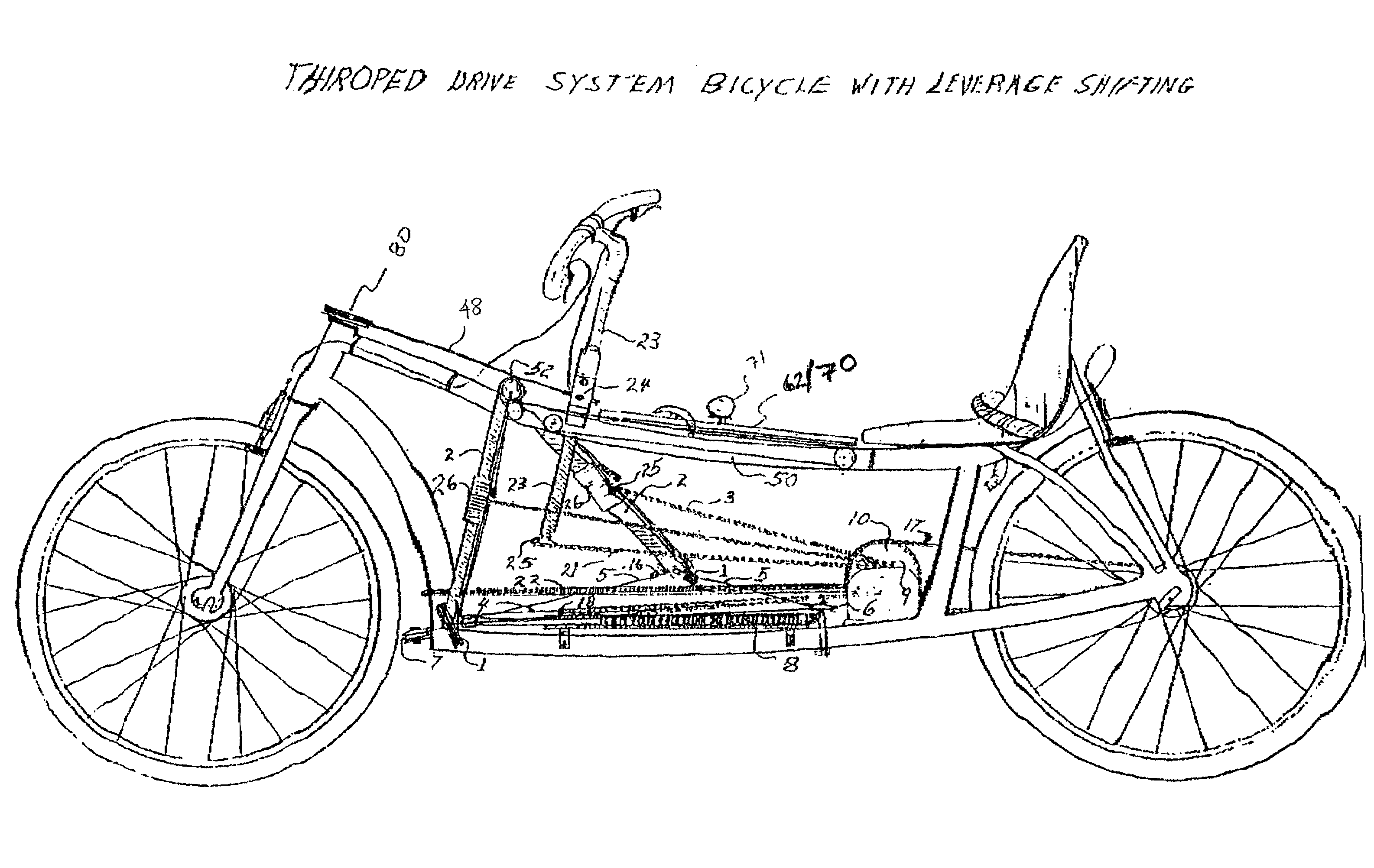
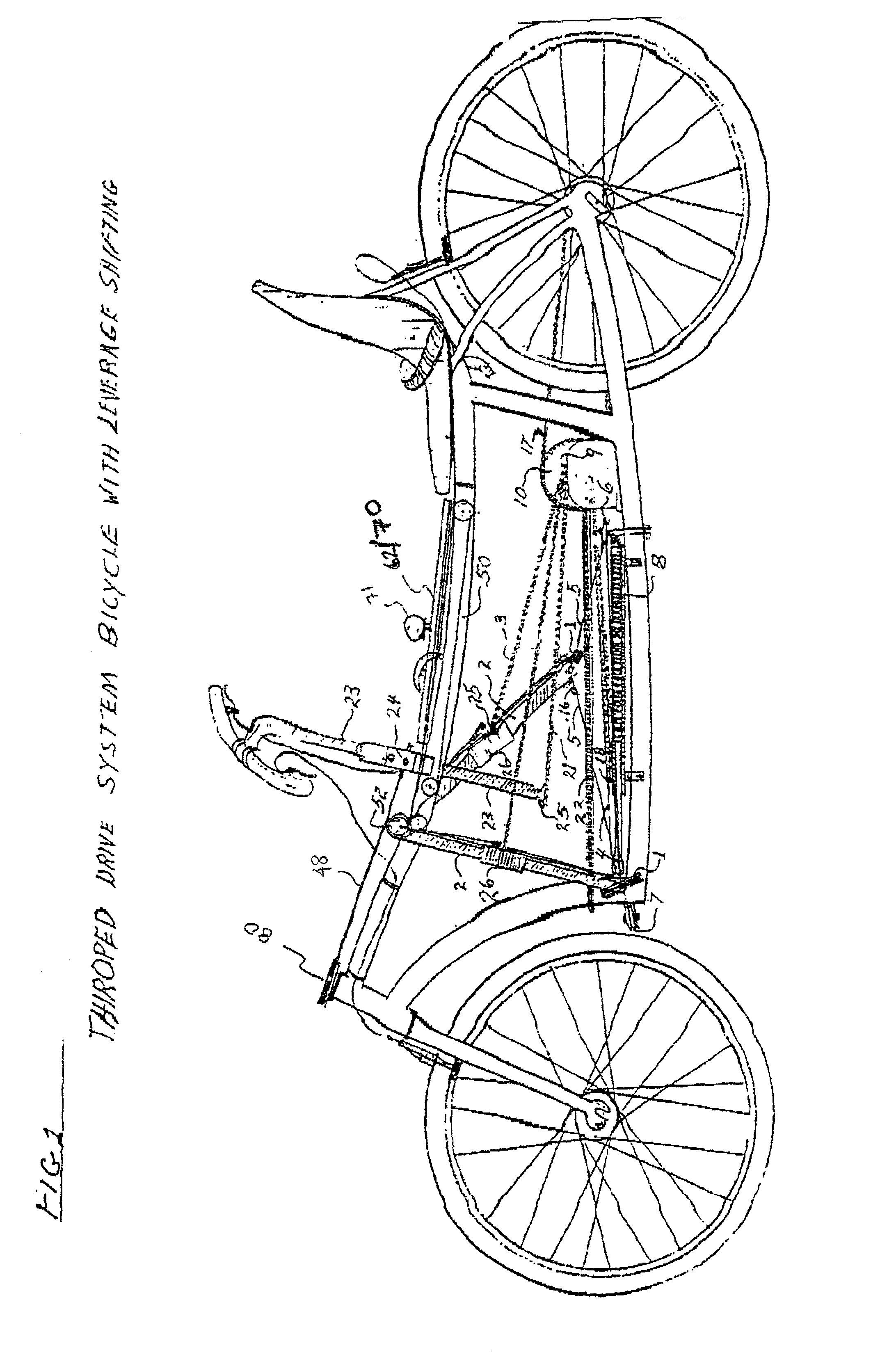
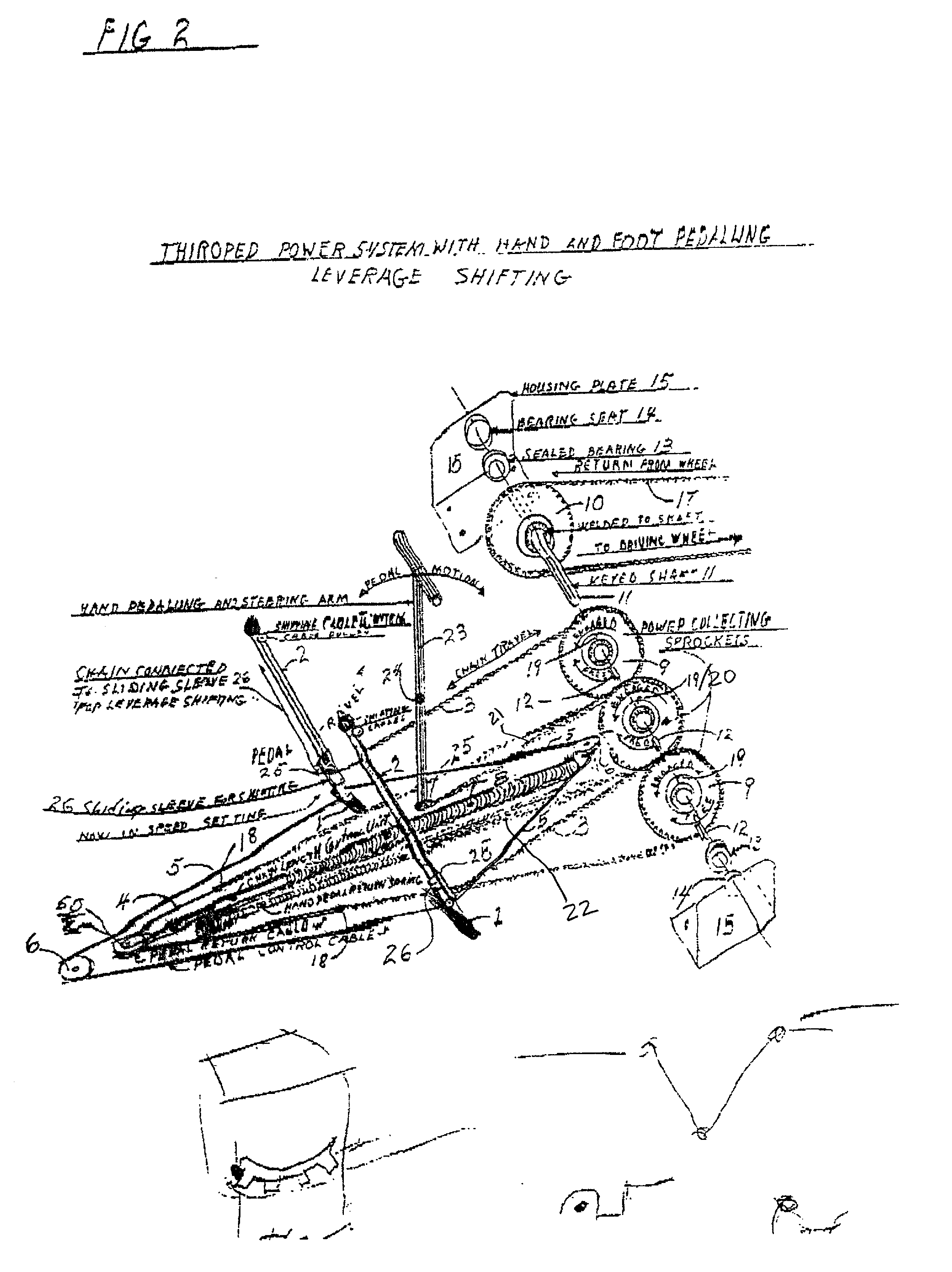
[0033] An overall drive system of sprockets and chains is best seen in the operational systems depicted in FIGS. 2 and 5. FIGS. 1-2 show the more basic, leverage shifting arrangement, and FIGS., 5A-5B show the drive system for the more advanced roller shifting arrangement. FIGS. 7-8 show the hand powered unit with a leverage and steering shaft 23, hinge assembly 24 and chain connector 25. Details of the hinge assembly 24 are shown in FIGS. 7A and 7B.

[0034] Those elements important to both systems are as follows: the pedals 1 act as levers (in contrast to conventional cyclic type pedals) and transfer the motion of the driver's legs onto the pedal arms 2 and then to those drive chains 3 that are in connection with a pair of power collecting or "free wheeling" sprockets 9 (20 is a similar free wheeling sprocket used for a hand powered unit described below). There is one freewheeling sprocket 9 associated with each pedal, thus there are two power collecting sprockets 9 in the power unit...


PUM


Abstract

A system for powering vehicles such as bicycles using leverage type pedals each connected to a freewheeling sprocket and then connected to a common drive shaft in the rear of the vehicle. A keyed shaft connects all free wheeling sprockets and provides for each sprocket to drive the keyed shaft in one rotational direction. A hand powering unit operates through a separate free wheeling sprocket and is also arranged like a lever in similar manner to the pedals. Lowered seating for horizontal movement of legs is preferred arrangement.

Description

CROSS-REFERENCE TO RELATED APPLICATIONS[0001] This application is a continuation-in-part application of U.S. patent application Ser. No. 09 / 667,609 filed on Sep. 22, 2000, the entirety of which is incorporated herein by reference.FIELD OF THE INVENTION[0002] The invention relates to the field of bicycles and in particular to a pedal powered unit with separate drive chains for each of the pedals to allow for continuous shifting; as well as a more horizontal position for the user's legs. The invention can also be used in tricycles with only minor modifications.[0003] The invention also describes new and improved methods for shifting for power and speed as well as a hand pedaling arrangement to allow for supplemental power to be supplied by the arms of the driver. The invention also provides for a lowered seating arrangement that allows the maximum force of the leg muscles to be exerted on the pedals of the bicycle.BACKGROUND[0004] Most present cycling designs provide for the driver to...

Claims


Application Information

Patent Timeline
Patent Type & Authority Applications(United States)
IPC IPC(8): B62M1/00B62M5/00
CPCB62M1/28Y10T74/20528B62M5/00
Inventor THIR, PETER
Owner THIR PETER
Why Eureka
Try Eureka