Apparatus and method for heating fluids

a technology of fluid heating and apparatus, applied in the direction of fluid friction for heating, heating apparatus, stoves or ranges, etc., can solve the problem that the amount of heat created in this way is likely to be quite small, and achieve the effect of broadening the number of occurrences, achieving the maximum power efficiency in performance, and reducing the risk of accidents

Inactive Publication Date: 2005-06-28
THOMA CHRISTIAN
View PDF23 Cites 61 Cited by
  • Summary
  • Abstract
  • Description
  • Claims
  • Application Information

AI Technical Summary

Benefits of technology

[0011]It is a still further object of the invention to alleviate or overcome some or all of the above described disadvantages of earlier devices for generating an improved shock wave by the cavitation implosion zones to maximum power efficiency in performance.
[0015]It is an aspect of this invention to be able to rapidly and successively alter and disrupt the path of fluid flowing between the rotating and stationary elements in the annular clearance, such that the deployment of openings or depression zones on the surface of the rotor acts to divert a quantity of the passing fluid into said openings or depression zones for the formation of cavitation vortices and their attendant shock waves and water hammer effects. The fluid once subjected to water hammer returns back to the annular passage with an increase in temperature and this continues in a continuous process until the fluid eventually reaches the exit passageway of the device. As such, each of said openings or depression zones becomes in effect individual heating chambers for the device. For certain applications, some or all of such individual heating chambers may be deeper in depth than deployed previously for the creation of an amplified cavitational effect by the device.

Problems solved by technology

Although some heating of the fluid is likely to occur naturally in the annular clearance, due to the shearing effect on the fluid between static and dynamic opposing boundary surfaces, the amount of heat created this way is likely to be quite small.

Method used


Image

  • Apparatus and method for heating fluids
  • Apparatus and method for heating fluids
  • Apparatus and method for heating fluids

Examples


second embodiment

DETAILED DESCRIPTION OF THE INVENTION

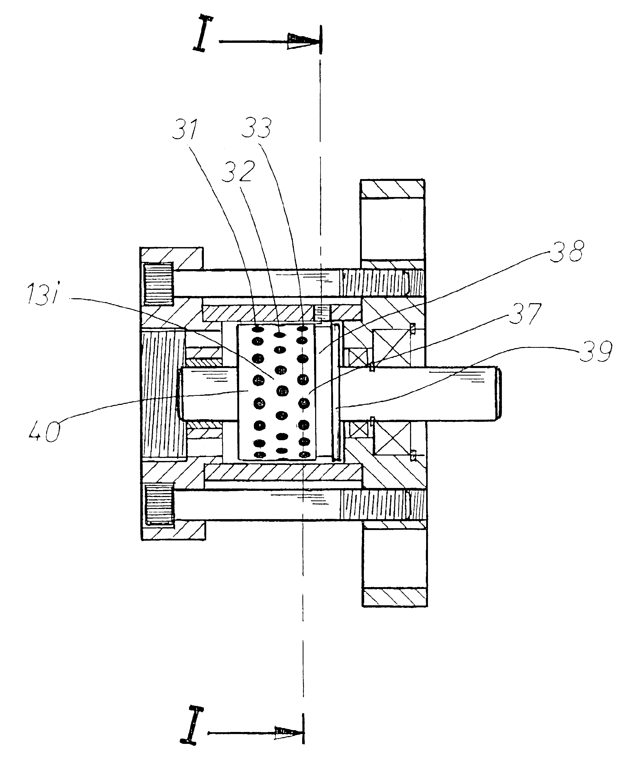
[0066]This embodiment of the present invention, depicted in FIG. 21, differs in only two major respects from the previously described first embodiment, firstly, in that the fluid entry connection is now routed through a port in the drive-shaft drive and secondly, the exterior shape of the rotor as well as the opposing interior shape in sleeve housing element are both inclined with respect to the longitudinal axis of the drive shaft.

[0067]Rotor 150 fixed to drive shaft 5i is provided with a conical male exterior surface 151 and sleeve housing member 3i is provided with a complimentary opposing female conical surface 152. As shown, three rows comprising a series of openings or depression zones, here in the formed of drilled holes such as holes denoted by reference numerals 155, 156 are disposed in said rotor 150. Sleeve housing member 3i is provided with a fluid exit connection 30i whereas the entry connection 10i in rear housing member 1i in this ...

third embodiment

DETAILED DESCRIPTION OF THE INVENTION

[0068]This embodiment of the present invention, depicted in FIG. 22, differs in two main respects from the previously described second embodiment. Firstly, the relatively short inclined inlet port at the end of the drive shaft is here replaced by a much longer longitudinal port in the form of a drilled hole which connects with a relatively shorter drilled hole. Secondly, the inlet fluid enters the annular chamber between rotor and housing at the greater diametric dimensioned end of the rotor.

[0069]Here one-piece forged rotor and shaft component, here referred to as the rotating component 175. The rotating component carries a plurality of openings 176 and includes a central longitudinal port 177 and radial port 178. The fluid inlet connection 10ii communicates through ports 177, 178 to axial clearance 170, and fluid entering axial clearance 180 flows past the various openings 176 in its transit through annular volume between rotating component 175...

fourth embodiment

DETAILED DESCRIPTION OF THE INVENTION

[0072]This embodiment of the present invention, depicted in FIG. 23, differs in one main respect from the previously described third embodiment, namely, the rotating component 190 comprising both the rotor and the drive shaft, is in this instance, provided with an outer surface 191 which is tapered in the opposite direction to the inclined surfaces shown in the second and third embodiments.

[0073]Rotating component 190 carries a plurality of openings 193 and includes a central longitudinal port 194 and radial port 195. The fluid inlet connection 10iii communicates through ports 194, 195 to axial clearance 196, and fluid entering axial clearance 196 flows past the various openings 193 in its transit through annular volume between rotating component 190 and housing sleeve 3iii. Once reaching circumferential fluid capturing groove 197, here reverted back to being located on the outer surface 191 of the rotating component 190, the heated fluid is expe...


PUM


Abstract

A fluid heating apparatus has a housing with a main chamber in which a rotor is situated. A drive shaft drives the rotor about a longitudinal axis of rotation. The housing has a fluid inlet and a fluid outlet, the fluid outlet communicating with an inlet region and the fluid outlet communicating with an exit region. The outer surface of the rotor forms one boundary for the fluid heat generating region and is confronted by the inner surface of the main chamber which is the other boundary. The fluid inlet is positioned closer to the longitudinal axis of the machine as compared to the fluid exit. The rotor is provided with at least one array of cavitation-inducing holes. Preferably, several rows of holes are configured on the rotor surface, some of which may have a depth dimension extending the radial width of the rotor.

Description

[0001]This application corresponds to the British application filed in the UK Patent Office on Jul. 3, 2003 in the name of the same inventor and having the same title, the entirety of which British application, including the drawings thereof, is hereby expressly incorporated by reference herein.BACKGROUND OF THE INVENTION[0002]The invention relates generally to the heating of liquids, and specifically to those devices wherein rotating elements are employed to generate heat in the liquid passing through them.[0003]Of the various configurations that have been tried in the past, types employing rotors or other rotating members are known, one being the Perkins liquid heating apparatus disclosed in U.S. Pat. No. 4,424,797. Perkins employs a rotating cylindrical rotor inside a static housing and where fluid entering at one end of the housing navigates through the annular clearance existing between the rotor and the housing to exit the housing at the opposite end. The fluid is arranged to ...

Claims


Application Information

Patent Timeline
Patent Type & Authority Patents(United States)
IPC IPC(8): F24J3/00
CPCF24V40/00
Inventor THOMA, CHRISTIAN
Owner THOMA CHRISTIAN
Why Eureka
Try Eureka