
Mounting apparatus for power supply

a technology for mounting apparatuses and power supplies, applied in the direction of electrical apparatus casings/cabinets/drawers, furniture parts, instruments, etc., can solve the problems of boring and time-consuming courses, and achieve the effect of restricting the vertical movement of the power supply

Inactive Publication Date: 2008-10-28
HONG FU JIN PRECISION IND (SHENZHEN) CO LTD +1
View PDF4 Cites 10 Cited by
  • Summary
  • Abstract
  • Description
  • Claims
  • Application Information

AI Technical Summary

Benefits of technology

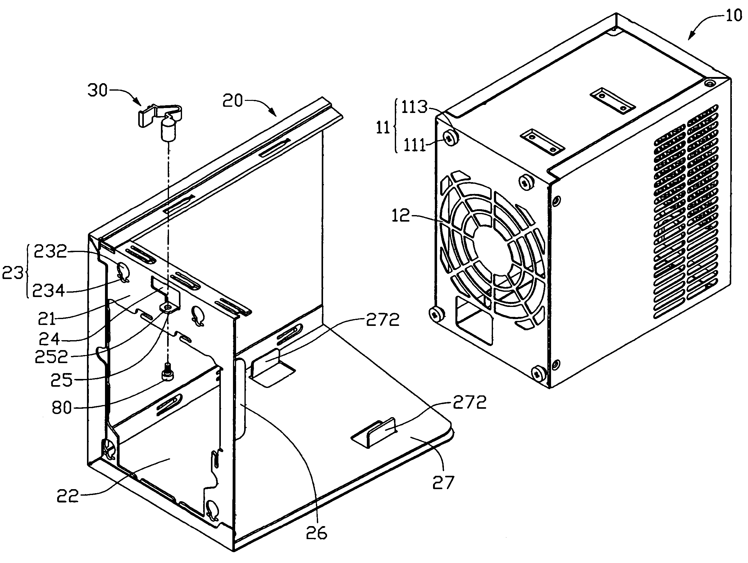
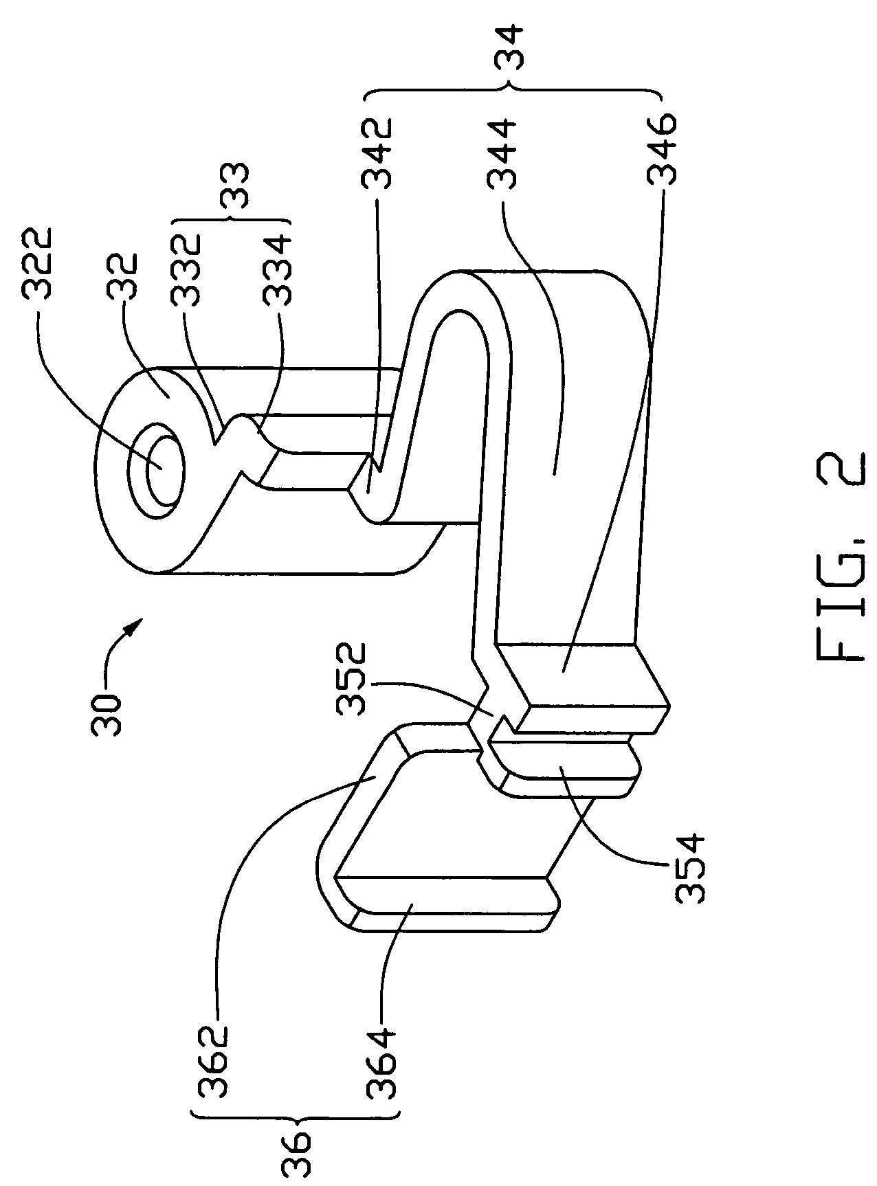
[0007]A mounting apparatus for a power supply in accordance with a preferred embodiment of the present invention includes a chassis, a plurality of sliding members adapted to attach to the power supply and a fastener member pivotably secured on the chassis. The chassis includes a support panel and a rear panel with a plurality of apertures defined therein. The fastener member comprises a clasp. The power supply is put on the support panel with the plurality of sliding members engaged in the plurality of apertures of the rear panel, the fastener member is rotated with the clasp of the fastener member engaging with the rear panel, the fastener member is fastened on the rear panel to restrict vertical movement of the power supply.

Problems solved by technology

The course is boring and time-consuming.

Method used


Image

  • Mounting apparatus for power supply
  • Mounting apparatus for power supply
  • Mounting apparatus for power supply

Examples


Embodiment Construction

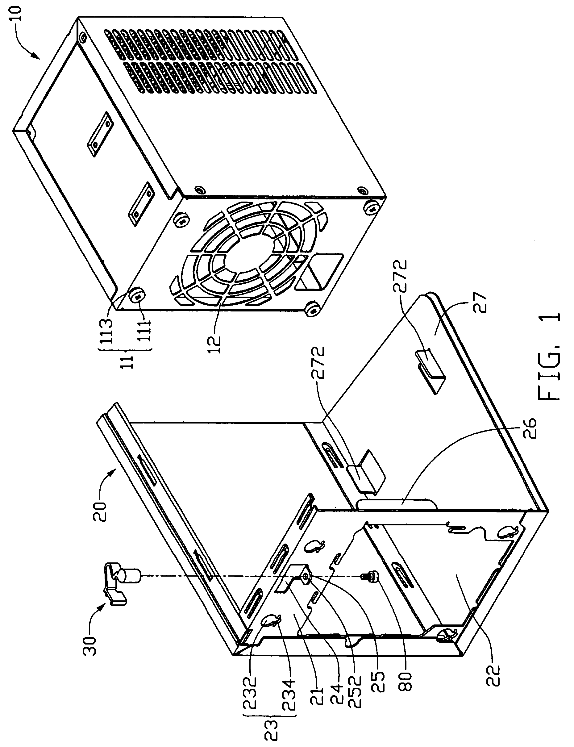
[0013]Referring to FIG. 1, a mounting apparatus for mounting a power supply 10 in an electronic device like a computer in accordance with a preferred embodiment of the present invention includes a chassis 20 and a fastener member 30. The chassis 20 includes a rear panel 21 and a support panel 27 for supporting a power supply 10 thereon.

[0014]An air grill is formed on a rear wall of the power supply 10. Four sliding members 11 used as first engagement means are secured at four corners of the rear wall of the power supply 10. The sliding member 11 includes a head 111 and a shank 113 exposed outside the rear wall of the power supply 10. A distance between the head 111 and the rear wall of the power supply 10 is adapted to engage in a hole defined in the rear panel 21.

[0015]The chassis 20 is partially shown in FIG. 1. The support panel 27 forms a pair of positioning pieces 272 thereon.

[0016]The rear panel 21 of the chassis 20 defines an opening 22 corresponding to the air grill of the p...


PUM


Abstract

A mounting apparatus for a power supply (10) includes a chassis (20), a plurality of sliding members (11) adapted to attach to the power supply and a fastener member (30) pivotably secured on the chassis. The chassis includes a support panel (27) and a rear panel (21) with a plurality of apertures (23) defined therein. The fastener member comprises a clasp (352). The power supply is put on the support panel with the plurality of sliding members engaged in the plurality of apertures of the rear panel, the fastener member is rotated with the clasp of the fastener member engaging with the rear panel, the fastener member is fastened on the rear panel to restrict vertical movement of the power supply.

Description

BACKGROUND OF THE INVENTION[0001]1. Field of the Invention[0002]The present invention relates to a mounting apparatus, and more particularly to a mounting apparatus for a power supply in a computer chassis.[0003]2. General Background[0004]Low-voltage direct current power is required for electronic components in a computer, such as a mother board, a hard disk drive. A power supply is often mounted in a computer chassis for converting alternating current to direct current and supplying the direct current to the computer.[0005]A conventional computer chassis adapted for mounting a power supply includes a rear panel which forms an opening thereof to expose the power supply. A plurality of holes are defined proximate the opening for extension of screws to fix the power supply on the computer chassis. However, when the power supply needs to be attached to or detached from the computer chassis, a screwdriver is needed to drive the screws in or off the holes defined in the power supply. The...

Claims


Application Information

Patent Timeline
Patent Type & Authority Patents(United States)
IPC IPC(8): H05K7/12
CPCG06F1/184G06F1/188
Inventor CHEN, YUN-LUNGSUN, DA-LONG
Owner HONG FU JIN PRECISION IND (SHENZHEN) CO LTD
Learn More