
Method for driving LCD device

a technology of liquid crystal display and driving method, which is applied in the direction of static indicating devices, non-linear optics, instruments, etc., can solve the problems of complex driving method for controlling the driving angle of the driving sub-pixel, the process of forming the sub-pixels the driving method for controlling the viewing angle of the sub-pixels, and the low viewing control effect. , to achieve the effect of narrow viewing angle, wide viewing angle and narrow viewing angl

Active Publication Date: 2007-07-05
LG DISPLAY CO LTD
View PDF4 Cites 19 Cited by
  • Summary
  • Abstract
  • Description
  • Claims
  • Application Information

AI Technical Summary

Benefits of technology

The patent describes a method for driving an LCD device in a fringe field switching (FFS) mode to achieve a wide viewing angle, and then in a viewing angle control (VAC) mode to achieve a narrow viewing angle by dividing the frame frequency period. This allows for improved viewing angles and better control over the display. The LCD device includes a plurality of gate and data lines, thin film transistors, and first and second common electrodes. The driving mechanism is operative to drive the LCD device in both the FFS mode and the VAC mode. The technical effect of this patent is to improve the viewing angles and control of LCD displays.

Problems solved by technology

However, there often is a low viewing control effect, and the process of forming the sub-pixels for controlling a viewing angle and the driving method for controlling the sub-pixels are complicated.
Hence, the driving method of controlling the viewing angle of the sub-pixels is complicated because a new electrode layer as a viewing control layer must be added and then a signal must be applied to the new electrode layer.

Method used


Image

  • Method for driving LCD device
  • Method for driving LCD device
  • Method for driving LCD device

Examples


Embodiment Construction

[0034] Reference will now be made in detail to the examples, which are illustrated in the accompanying drawings. Wherever possible, the same reference numbers will be used throughout the drawings to refer to the same or like parts.

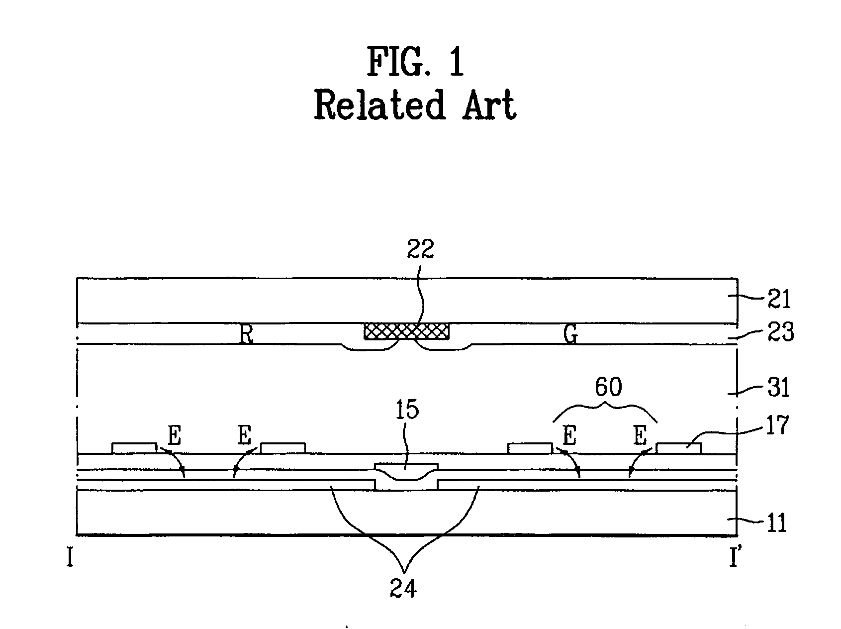
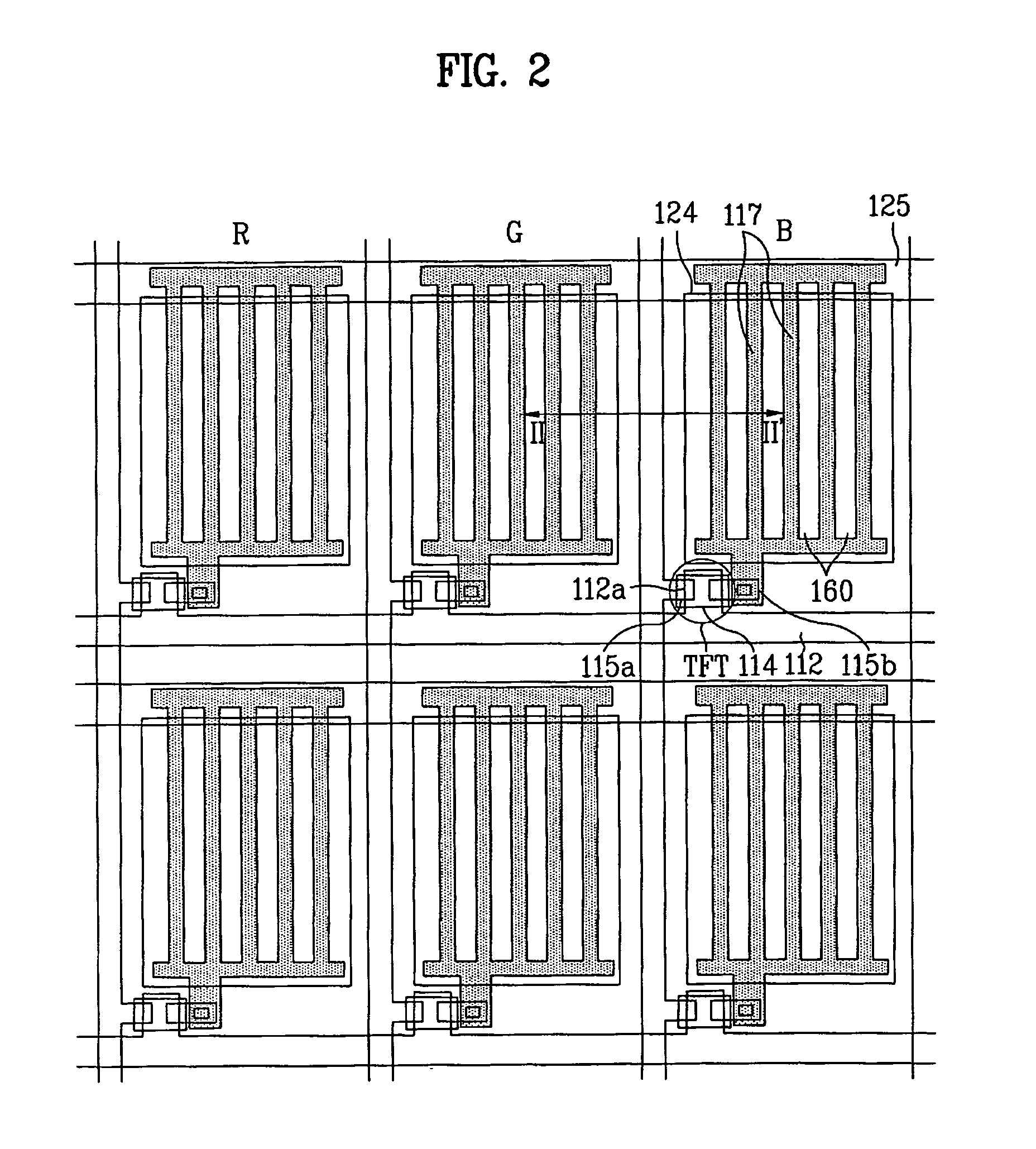
[0035] As shown in FIGS. 2 and 3, the LCD device includes a TFT array substrate 111 and a color filter array substrate 121, wherein the TFT array substrate 111 is bonded to the color filter array substrate 121 by interposing a liquid crystal layer 131 in between. The TFT array substrate 111 includes thin film transistors serving as switching elements in each sub-pixel, and first common electrodes 124 and pixel electrodes 117. The first common electrodes 124 and the pixel electrodes 117 form a fringe field. The color filter array substrate 121 includes second common electrodes 126 for controlling a viewing angle.

[0036] In more detail, the TFT array substrate 111 includes gate lines 112 and data lines 115 insulated from each other by a gate insulating laye...


PUM


Abstract

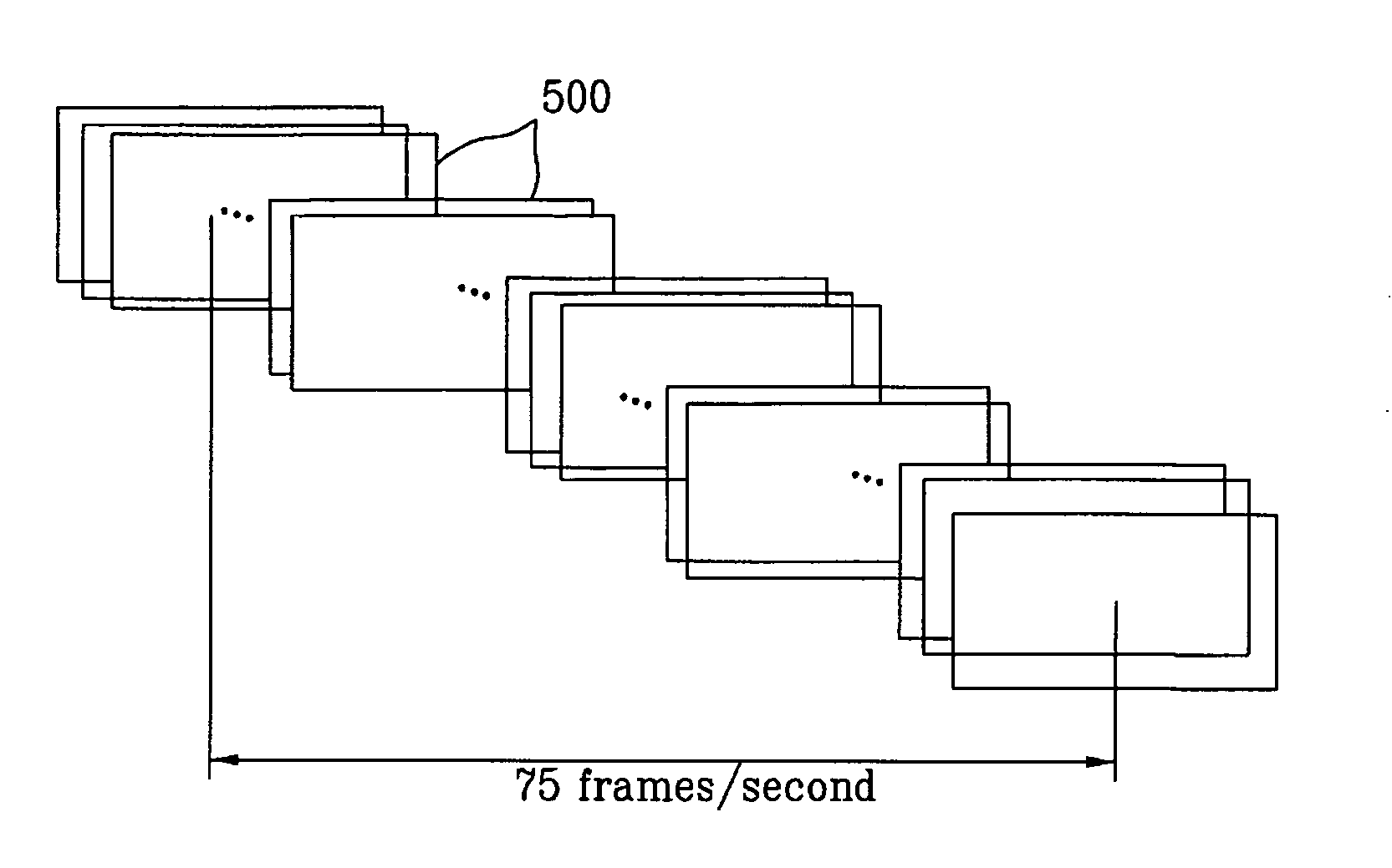
An LCD device is disclosed in which the LCD device is driven in an FFS mode and a VAC mode during a frame frequency period to obtain a narrow viewing angle. The method for driving the LCD device includes driving the LCD device in an FFS mode during a frame frequency period to obtain a wide viewing angle, and driving the LCD device in both the FFS mode and a VAC mode during the frame frequency period by dividing the frame frequency period, thereby obtaining a narrow viewing angle.

Description

[0001] This application claims the benefit of Korean Patent Application 2005-0133926, filed on Dec. 29, 2005, which is hereby incorporated by reference in its entirety. BACKGROUND [0002] 1. Technical Field [0003] The technical field relates to liquid crystal display (LCD) devices, and more particularly, to a method for driving an LCD device, in which the LCD device is driven in a fringe field switching (FFS) mode during a frame frequency period to obtain a wide viewing angle while sub-frames divided from a frame are sequentially driven in both an FFS mode and a viewing angle control (VAC) mode during the frame frequency period to obtain a narrow viewing angle, thereby resulting in that a narrow viewing angle is obtained in view of time average. [0004] 2. Discussion of the Related Art [0005] Recently, active matrix LCD devices have become widely used in flat TVs, portable computers, monitors in accordance with their developing performance. [0006] Generally used among the active matri...

Claims


Application Information

Patent Timeline
Patent Type & Authority Applications(United States)
IPC IPC(8): G09G3/36
CPCG02F1/1323G09G3/2018G09G2320/028G09G2300/0426G09G3/3648G02F1/133G02F1/1343
Inventor JIN, HYUN SUKJANG, HYUNG SEOK
Owner LG DISPLAY CO LTD
Learn More