Speed reduction warning system

a technology of speed reduction and warning system, which is applied in the direction of vehicle components, signalling/lighting devices, optical signalling, etc., can solve the problems of prior art system providing false signals, not enough information for the operator of trailing vehicles to safely maneuver, and giving erroneous signals

Inactive Publication Date: 2007-07-12
ROSER CHARLES R
View PDF2 Cites 19 Cited by
  • Summary
  • Abstract
  • Description
  • Claims
  • Application Information

AI Technical Summary

Benefits of technology

[0009]The present invention is an enhancement to a vehicle safety system that senses vehicle deceleration rate and upon reaching preset limits flashes an illumination device at different rates signaling the operator following the vehicle to the rate of deceleration. The speed reduction warning system of the current invention generally includes a processing unit, an input to the processor that senses deceleration or acceleration rate from the odometer of the vehicle, and an output illumination device. The illumination device includes an indicator that flashes at varying rates controlled by the processor. The processor includes storage having a plurality of ranges stored that are the deceleration rates that the system responds to. In application, with the vehicl...

Problems solved by technology

However, a typical brake light signaling is either on (illuminated) or off and does not indicate the degree of vehicle deceleration.
This may not be enough information for the operator of a trailing vehicle to safely maneuver to avoid a rear end collision.
However, the systems...

Method used


Image

  • Speed reduction warning system
  • Speed reduction warning system

Examples


Embodiment Construction

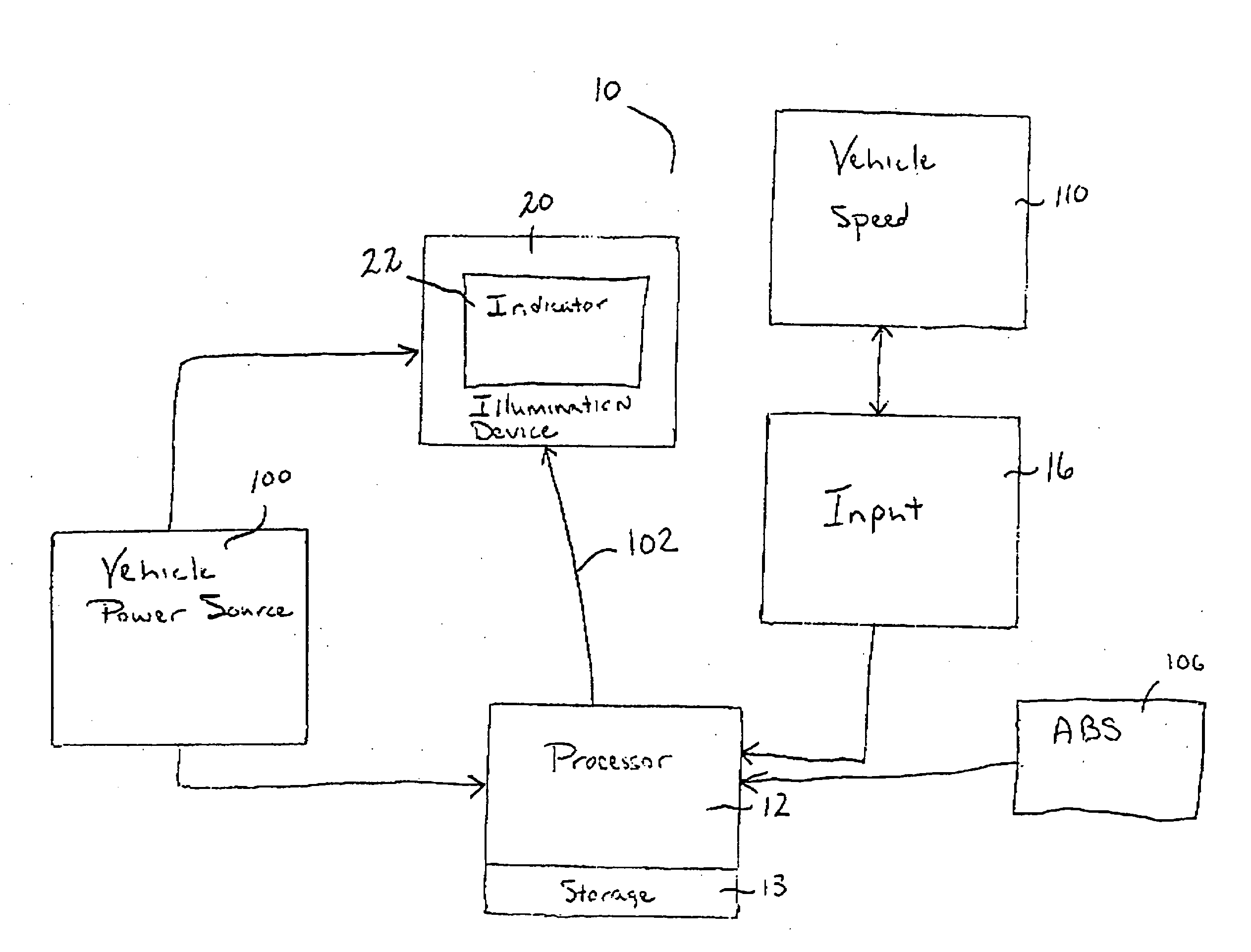
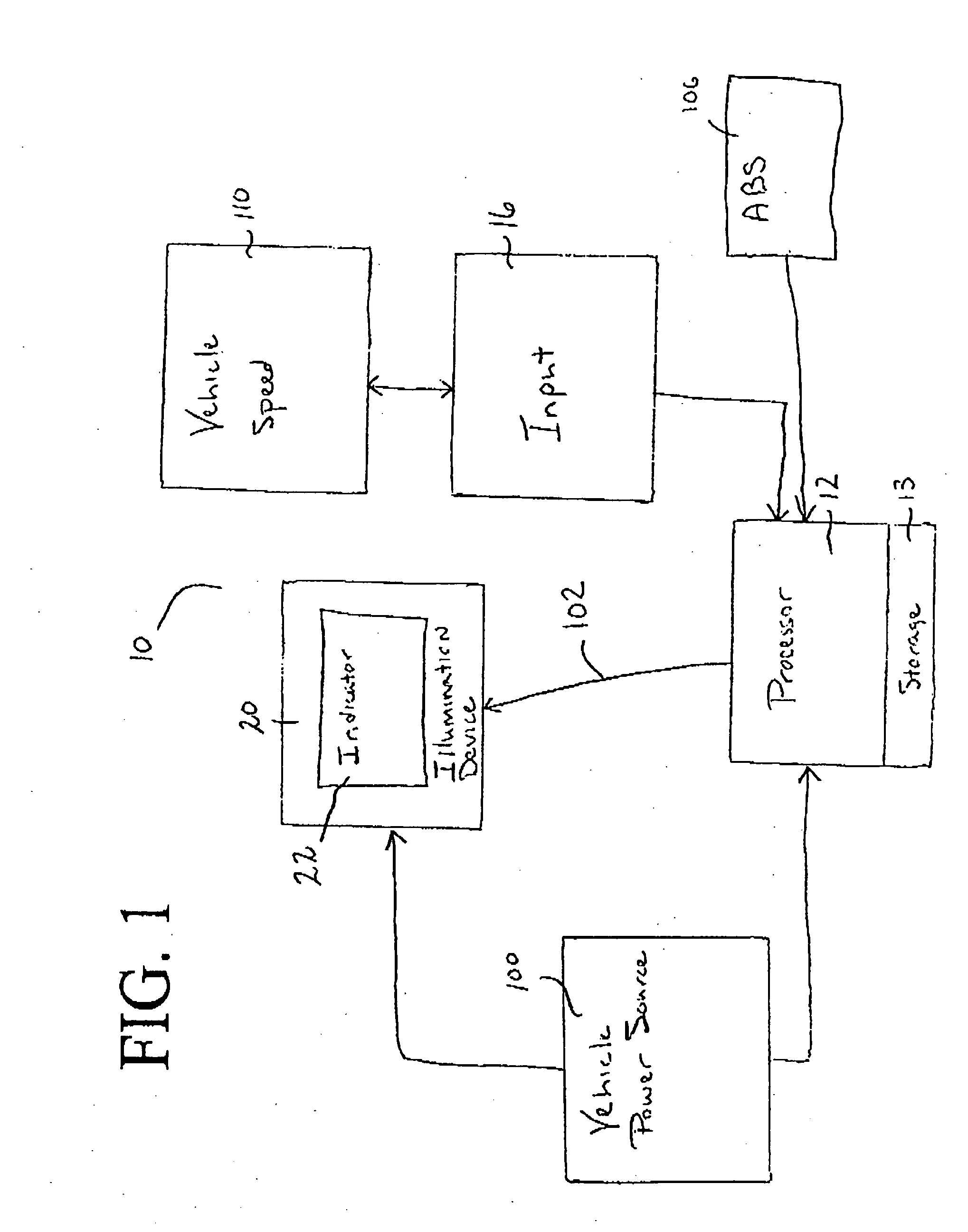
[0011]In accordance with the present invention, a speed reduction warning system is disclosed. The speed reduction warning system is directed to a vehicular system that indicates to a trailing vehicle the degree of vehicle deceleration of the vehicle in front. Specifically, the speed reduction warning system of the present invention improves normal braking signaling to the operator of a trailing vehicle by detecting the rate of deceleration and indicating this information through flashing of an illumination device and further, flashing the illumination device at different rates according to the deceleration rate. In the broadest context, the speed reduction warning system of the present invention consists of components configured and correlated with respect to each other so as to attain the desired objective.

[0012]It should be noted that the speed reduction warning system that will be described herein is independent of the vehicle's braking system.

[0013]FIG. 1 illustrates the overal...


PUM


Abstract

A speed reduction warning system that senses vehicle deceleration rate and upon reaching preset limits flashes an illumination device at different rates signaling the operator following the vehicle to the rate of deceleration. The system generally includes a processing unit, an input to the processor that senses deceleration or acceleration rate from the odometer of the vehicle, and an output illumination device. The illumination device includes an indicator that flashes at varying rates controlled by the processor. The processor includes storage having a plurality of ranges stored that are the deceleration rates that the system responds to. In application, with the vehicle in motion, the deceleration or acceleration rate of the vehicle is detected by the input device and supplied to the processor. A value is calculated by the processor representing whether the vehicle is decelerating and if so, the rate of deceleration. If the value is within one of the ranges in storage, the processor sends a corresponding output signal to the illumination device. Once the vehicle is stopped or begins to accelerate the output signal is extinguished by the processor, automatically. The system can further include means such that the indicator of the illumination device activates a selected illumination when the vehicle's anti-lock brake system is applied, or a steady illumination when the vehicle's speed is below 5 mph.

Description

CROSS REFERENCES TO RELATED APPLICATIONS[0001]U.S. Provisional Application for Patent No. 60 / 758,913, filed Jan. 12, 2006, with title “Speed Reduction Warning System” which is hereby incorporated by reference. Applicant claims priority pursuant to 35 U.S.C. par. 119(e)(i).STATEMENT AS TO RIGHTS TO INVENTIONS MADE UNDER FEDERALLY SPONSORED RESEARCH AND DEVELOPMENT[0002]Not ApplicableBACKGROUND OF THE INVENTION[0003]1. Field of the Invention[0004]The present invention relates generally to a vehicle safety warning system, and more particularly to a warning system that improves normal braking signaling by detecting the rate of deceleration and indicating this information through flashing of an illumination device.[0005]2. Brief Description of Prior Art[0006]Most vehicles are equipped with rearward facing visual signaling devices to indicate when the vehicle's braking system is activated. However, a typical brake light signaling is either on (illuminated) or off and does not indicate the...

Claims


Application Information

Patent Timeline
IPC IPC(8): B60Q1/50
CPCB60Q1/448B60Q1/444
Inventor ROSER, CHARLES R.
Owner ROSER CHARLES R
Why Eureka
Try Eureka